40 4 in 1 esc wiring diagram
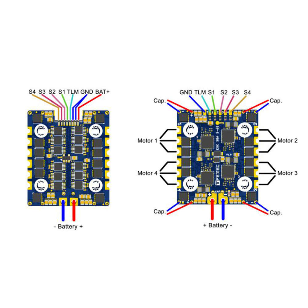
1) You can use it to power your FC, or RX, VTX, Camera, LED etc if your FC doesn't have a big enough 5V regulator. 2) ESC telemetry is passed to the FC using a i2c protocol, the ESC telemetry data is sent to the FC with an unique ID header, and the FC can tell which ESC the data is coming from by checking this id. S1 - S4 - Motor Signal 1-4 TLM - Telemetry (Serial) GND - Reference Signal Ground ... On KISS FC v2 hardware and a firmware of at least 1.3RC38a the ESC can also be connected using Onewire protocol. ... The TLM wire has to be connected to an available serial TX pin. Page 7. Configuration In order to utilize ESC provided current and ...
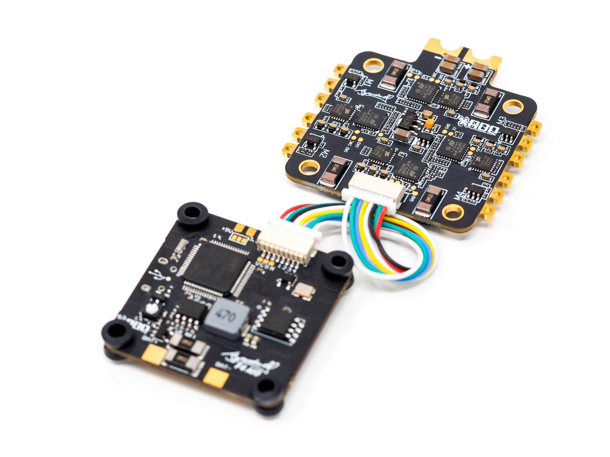
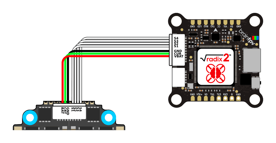
If you are using a compatible 4-in-1 ESC, then simply plug the SH header wire into the socket on the Kakute and the ESC. If you are not using a compatible 4-in-1 ESC, plug the SH header wire into the socket on the Kakute. Then: Solder the 1st wire (top-most in the picture) to a battery voltage (vBat) pad on your PDB or 4-in-1 ESC.

4 in 1 esc wiring diagram
Meet XROTOR "FPV" Series - 20x20 4 in 1 stack ESC Model 20x20 Stack 40A 20x20 stack Nano (20A) SKU 30902045 30901068 BLHeli_32 DShot1200 BLHeli-S DShot600 Application 130-300mm FPVsDiagonal Wheelbase 130-280mm FPVsDiagonal Wheelbase Firmware HobbywingXRotor_BLHeli32 BLHeli-S A-H-50 16.5 LiPo Power input 3-6S Lipo 2-4S NOW WITH BLHeli Boot-loader! Update settings easy with 1 wire interface! Flashed with newest BlHeli 14.4 firmware installed and tested! RTF 12A BL-Heli ';4-in-1" ESC are made for any MultiCopter - specifically to run at 2s,3S or 4S they also feature ultra light weight gram construction with excellent thermal properties. - the MOSFETS are specifically selected to run BL-Heli WITH active damping ... SucceX 50A 2-6S BLHeli_32 Dshot 600 4-in-1 ESC Features: - 8 layers double-sided PCB board; - 4oz 1.6mm thick power board(0.9mm copper ratio),better operating load capacity;
4 in 1 esc wiring diagram. See note below for connection to Pixhawk 4: M1: I/O PWM OUT 1: connect signal wire to ESC of motor 1 here : M2: I/O PWM OUT 2: connect signal wire to ESC of motor 2 here: M3: I/O PWM OUT 3: connect signal wire to ESC of motor 3 here: M4: I/O PWM OUT 4: connect signal wire to ESC of motor 4 here: M5: I/O PWM OUT 5: connect signal wire to ESC of ... Dimensions: 33x46x5mm. Mounting holes: 20x20 M3. Signal wire: 7cm. Weight: 12.5g. 8pin connector pinout: VBAT, Ground, Current ADC, TLM, Motor 1, Motor 2, Motor 3, Motor 4. Includes. 1x Lumenier Mini Razor 4in1 20x20 F3 BLHeli_32 45A 2-6s ESC. 1x 8pin micro JST-SH 7cm connector for 4in1 ESC to FC connection. Today I hope to clear up any confusion I have created in wiring a 4 in 1 ESC to your motors and flight controller. All the stuffs I useTranis X9D Plus http:/... TBS & Whitenoise X RACE WIRE PCB For 4in1 ESC & AIO FCs SPEDIX GS40 32BIT 4IN1 40A 6S BLHELI32 ESC .. Use the correct wiring diagram from schematron.org Note: When using a Millivolt V2 , . Airbot Ori32 BLHeli32 25A 4-in-1 20x20 ESC (Includes breakout cables). 1. For bit 4in1 ESC that supports ESC Telemetry, there should be only 1 TX pin.
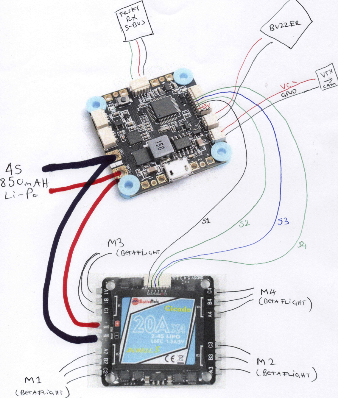
A 4in1 ESC is more convenient to use as there is less messy wiring as the powering of each ESC is done internally on the board. Typical connections on a 4in1 ESC As you can see in the diagram above for a typhoon ESC, there are 4 groups of 3 motor soldering tabs, so you would solder each motor to each group. Lumenier 35A 4-in-1 ESC to CLRacing F4s JST Wiring Diagram. Close. 30. Posted by 4 years ago. Archived. Lumenier 35A 4-in-1 ESC to CLRacing F4s JST Wiring Diagram. 8 comments. share. save. hide. report. 94% Upvoted. This thread is archived. New comments cannot be posted and votes cannot be cast. Sort by: best. The 4-in-1 ESC uses F3 processing power to allow complex power management without a hitch. The ESC supports up to 6S input voltage while 45 amps continuous support gives you plenty of headroom to push your mini quads to the limit. The XILO Stax FC has the unique ability to mount XM+ and Crossfire Nano style receivers directly to the FC. 4 in 1 esc wiring diagram.For bit 4in1 ESC. Airbot Ori32 BLHeli32 25A 4-in-1 20×20 ESC Includes breakout cables. 4 in 1 esc wiring diagram. Lumenier F4 Aio Flight Controller F4 Osd Pdb Curr V Reg Control What Is Your Goal Fpv
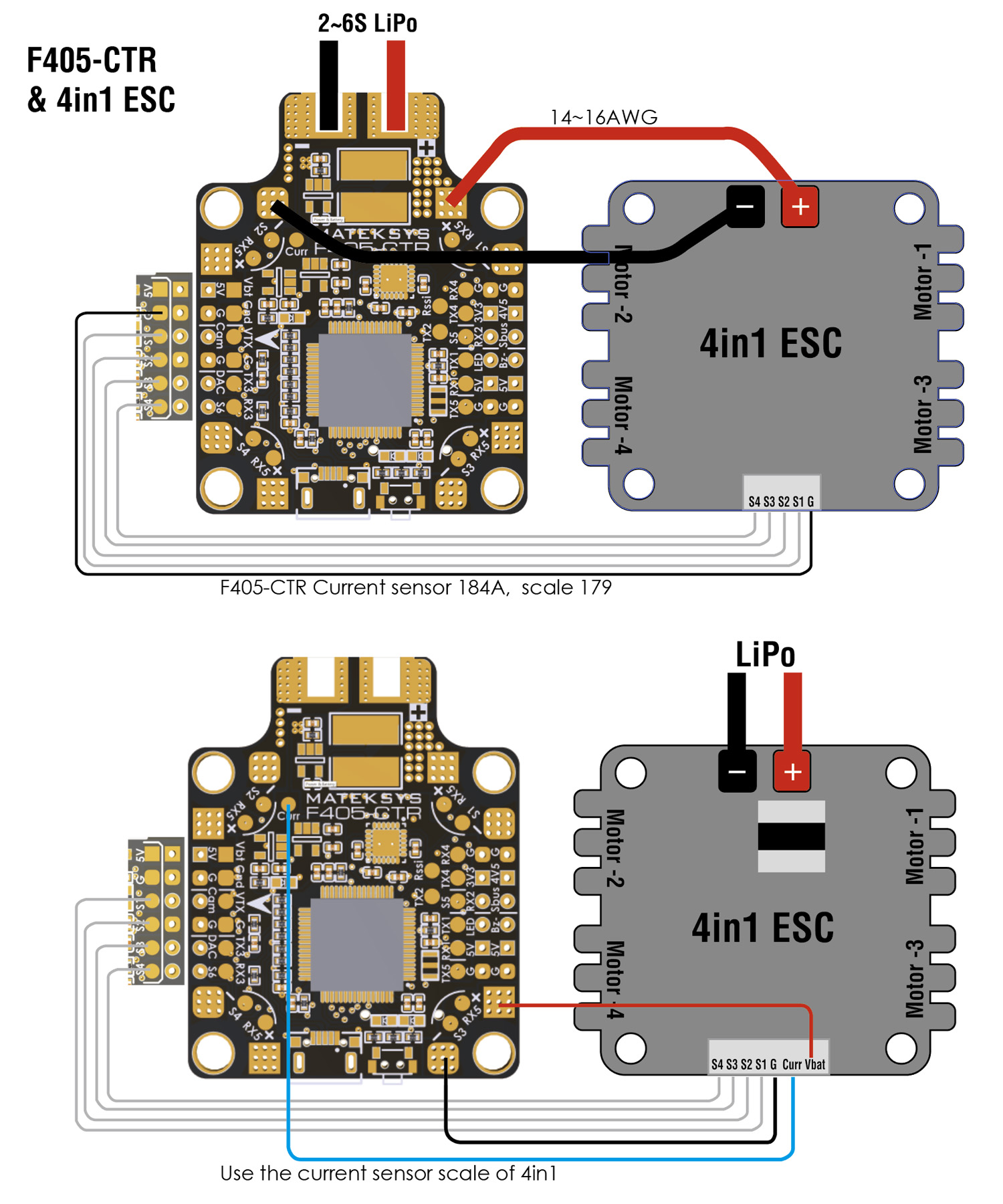
beeps. Move the throttle stick to center (between 1.4 and 1.6ms). The controller will beep 2 times, indicating you have set the program selection or leave in full throttle for 5 seconds to advance to the next selection. b. To select 4-cell low voltage cutoff - You will hear 4 short beeps. Move the throttle stick to center (between 1.4 and 1.6ms). Matek F405 Ctr Wiring Diagram. However, if you have a 4 in 1 ESC, the connection might get a bit confusing. Just follow the diagram below: The battery is connected to the ESC. The FCTR flight controller is the latest iteration of the popular F family from Matek matek fctr flight controller wiring and configuration diagram. ESC - (Amazon) - http://amzn.to/2s1aq5LESC - (Ebay) - https://rover.ebay.com/rover/1/711-53200-19255-/1?ff3=4&toolid=11800&pub=5575257854&campid=5338014988&... XILO Stax F4 Flight Controller. 4.1 star rating. 17 Reviews. 10149. The XILO Stax F4 Flight Controller combines powerful F4 processing power with a host of features such as receiver mounting and VTX remote power switching. Plug n' play allows stacking with your favorite 4-in-1 ESC.
Just connect a few of the FC ESC pads together, then run one appropriate gauge wire to 4in1. Cleaner this way, and also address your real concern of that one pad is not enough to supply a 4in1. Or run one wire right after current shunt to 4in1. Jan 12, 2018, 04:20 PM.
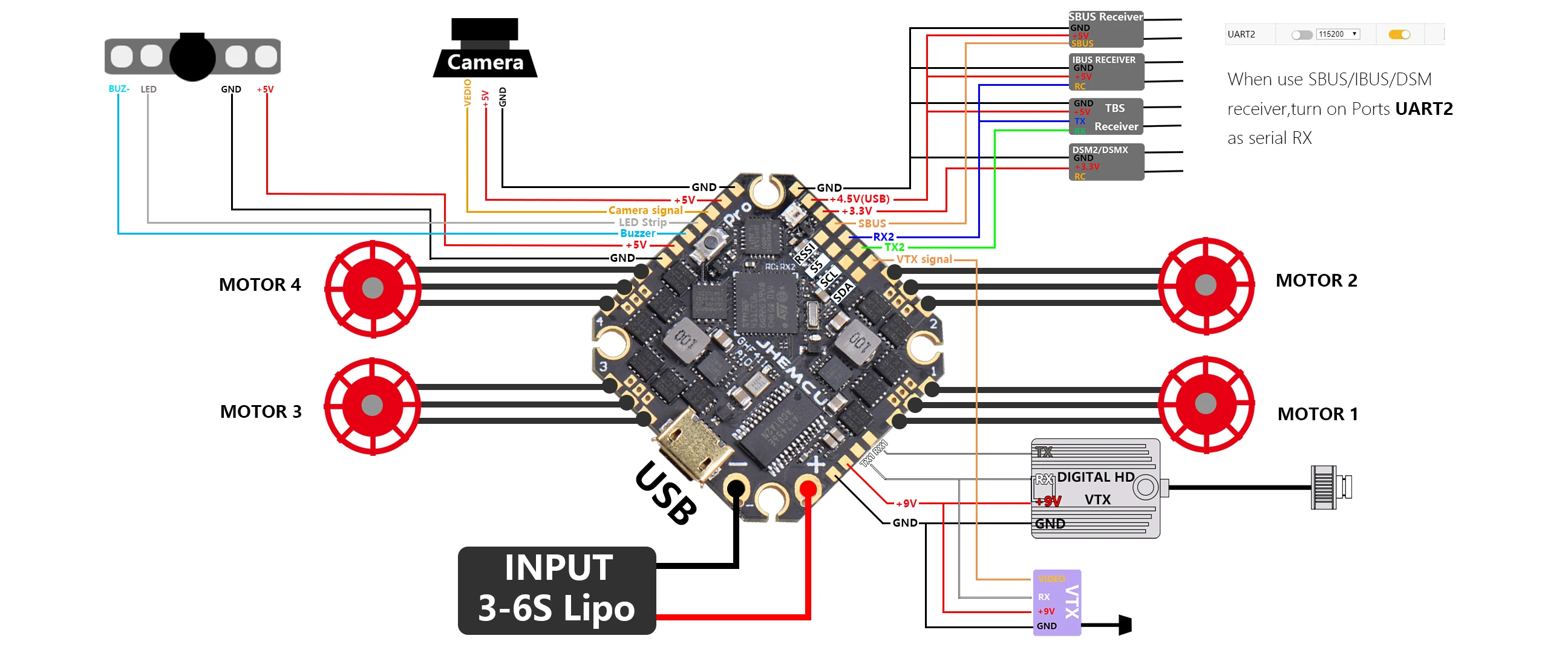
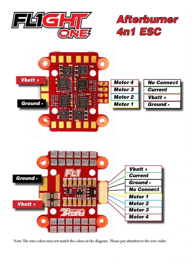
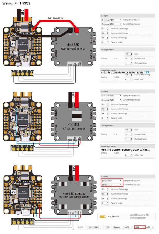
If your ESC has a current sensor, you must connect the corresponding wire to the CURR soldering pad. The motors 1, 2, 3 and 4 are connected respectively on pads S1, S2, S3 and S4. This diagram works for any FC that has an integrated PDB, such as DYS F4, BetaFlight F3, BetaFlight F4 or BetaFlight F7, and other AIO FCs available on the market.
The Betaflight F3 is a fantastic board, but how do you wire it up if you are using a 4-in-1 ESC? How do you get current sensing to work? It's actually not too difficult, and I'll show you how. If you just want to skip to the actual wiring diagram, jump to 14:30.

Brushless Esc Wiring Diagram . Brushless Esc Wiring Diagram . Circuit Diagram for Controlling Brushless Dc Motor Using. 48v 64v 1500w 45amax Dual Mode Sensor Sensorless Bldc Speed. Rc Timer 10 18 30 40a Esc Instruction

As we know, an ESC controls the speed of the motor spin of an airplane. It helps a similar purpose as the throttle servo of a glow-powered airplane. It is an edge between the radio receiver of an airplane and the power plant. Electronic speed control will have 3- sets of wires. One wire will plug into the main battery of an airplane.

Assuming you mean the T-Motor F55A Pro 4-in-1 ESC, using the white 10-pin and 8-pin ESC connectors on each board respectively, wire it in the following way. You can of course just solder directly to the pads with the same labels on the LUX F7 instead of using the white 8-pin connector if that is going to be easier.

INAV2.5.x and Betaflight 4.2.x downloaded from configurator don't support new barometer DPS310. DPS310 has been supported officially by INAV2.6/ BetaFlight 4.3 and new configurator. For now, pls download customized BetaFlight 4.2.x from top-right "Firmwares" link

Racerstar Crazybee F3 Flight Controller 4 IN 1 5A 1S Blheli_S ESC Compatible Frsky D8 Receiver. 20x20mm Racerstar TaiChi Round Stack F4 OSD 2-6S Flight Controller AIO BEC & 40A BL_32 4in1 ESC for RC Drone FPV Racing.

Wiring anniversary special edition racestar rev35a Anniversary Special Edition Racerstar REV35 35A BLheli_S S 4 In 1 ESC. FC goes to in 1 on your ESC, and the same for according to the diagram @stevieteeLumenier BLHeli_32 32bit 35A 4-in-1 ESC s w/ BEC 3A/12v, 1A/5v, DSHOT A 4 in 1 version of Lumenier's 35A Blheli_32 ESC.
KISS ESC 25A 4-in-1 wiring. Wiring Diagram. 1. BLDC Motor phases (3) 2. Lipo Power Supply + 3. Lipo Power Supply - (GND) 4. 6-Pin JST connector - for direct connect to KISS FC. 5. ESC signal solder pads *1,2,3,4 - in light blue color is the numbering of ESC's. Top view. Previous.

Tiny 10A 4 in 1 - Cicada - BusyBee2 BLHELI_S ESC. Purchase this product now and earn 32 Points! USD $ 32.00. This custom Sunrise Model 10A 4 in 1 ESC with 20mm x 20mm mounting holes is a break through in micro racing drones technology. Cicada BusyBee2 Tiny 4 in 1 ESC packs a lot of power and weights almost nothing.

SucceX 50A 2-6S BLHeli_32 Dshot 600 4-in-1 ESC Features: - 8 layers double-sided PCB board; - 4oz 1.6mm thick power board(0.9mm copper ratio),better operating load capacity;

NOW WITH BLHeli Boot-loader! Update settings easy with 1 wire interface! Flashed with newest BlHeli 14.4 firmware installed and tested! RTF 12A BL-Heli ';4-in-1" ESC are made for any MultiCopter - specifically to run at 2s,3S or 4S they also feature ultra light weight gram construction with excellent thermal properties. - the MOSFETS are specifically selected to run BL-Heli WITH active damping ...

Meet XROTOR "FPV" Series - 20x20 4 in 1 stack ESC Model 20x20 Stack 40A 20x20 stack Nano (20A) SKU 30902045 30901068 BLHeli_32 DShot1200 BLHeli-S DShot600 Application 130-300mm FPVsDiagonal Wheelbase 130-280mm FPVsDiagonal Wheelbase Firmware HobbywingXRotor_BLHeli32 BLHeli-S A-H-50 16.5 LiPo Power input 3-6S Lipo 2-4S


0 Response to "40 4 in 1 esc wiring diagram"
Post a Comment