41 cantilever beam free body diagram
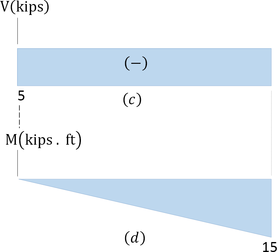
Solution Free body diagram Shear diagram Moment diagram Draw the shear and moment diagrams for the cantilever beam (units KN,m). The International Information Center for Structural Engineers Draw the free body diagram: By taking the moment at B, ... A cantilever beam is loaded as shown. Determine all reactions at support A. 5 kN/m 2 m 2 m 1 m A 20 kN 3 4 15 kNm EXAMPLE 3 . Draw the free body diagram:
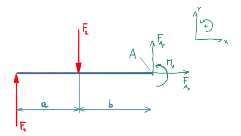
that the free-body diagram serves the purpose of focusing accurate attention on the action of the external forces; therefore, the diagram should not be ... Cantilever . a b L B F A F . University of Arizona J. H. Burge 20 X and Y components . Cantilever . L F ... Assuming the beam does not fall, what is the direction
Cantilever beam free body diagram
Draw the free body diagram for the cantilevered beam. If a beam is cantilevered it has a fixed support at one end which is the right end for this beam the beam weighs 150 lbft and the weight of the beam acts through its centroid. The wall holds the cantilever beam. All the reaction components will be experienced only on the fixed end. The above beam design and deflection equations may be used with both imperial and metric units. As with all calculations/formulas care must be taken to keep consistent units throughout with examples of units which should be adopted listed below: Notation. FBD = free body diagram; SFD = shear force diagram; BMD = bending moment diagram Figure-3: Bending and Shear Force Diagram of Cantilever Beam with Point Load at Free End The shear force at the fixed support A is determined by keeping the section at A, which gives the shear force Ra=W; and moment Ma = W.l. based on which the shear force and bending moment diagram are developed.
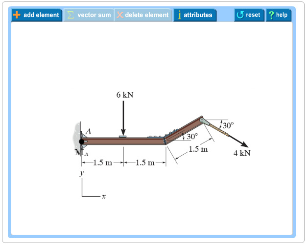
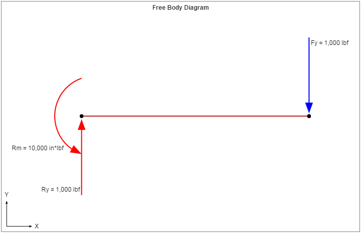
Cantilever beam free body diagram. Free-Body Diagram of Beam: The beam is fixed at point A. Therefore, there are two reaction forces and one reaction moment at this point as shown below. We assume a direction for each reaction load. Also to simplify the calculations, the distributed force is represented by its resultant acting at its centroid., https://goo.gl/P5AUbb for more FREE video tutorials covering Engineering Mechanics (Statics & Dynamics)The key objective of this video is to consider support... Advanced Math questions and answers. For the following cantilever beam, draw the shear and bending moment diagrams. You will need to show appropriate calculation and free body diagrams to support the diagram Please clearly mark the values/points on shear and bendng moment diagrams. 3 KN 6 kN/m B IA 1.5 m 1.5 m. Any changes made will automatically re-draw the free body diagram any simply supported or cantilever beam. The beam reaction calculator and Bending Moment Calculations will be run once the "Solve" button is hit and will automatically generate the Shear and Bending Moment Diagrams.
Cantilever beams and simple beams have two reactions (two forces or one force and a couple) and these reactions can be obtained from a free-body diagram of the beam by applying the equations of equilibrium. Such beams are said to be statically Like the portal frame example, the free body diagrams in Figure 7.10 are annotated with numbers in grey circles to show a suggested order for solving all of the unknown forces. Of course, as before, step 0 and step 1 consist of known values, either caused by external forces or the previous storey (for step 0) or the column axial forces that were solved using the cantilever method assumptions ... Free body diagrams may not seem necessary in the relatively simple current applications, but as problems become more complex, their usefulness increases. The following is the process for determining the reaction at the wall for a cantilever beam. A FBD is first drawn of the beam. Next, cut the beam free from the wall and replace the wall with ... Tip-Loaded Cantilever Beam: Equilibrium P Free body diagrams: •statically determinant: support reactions R, M 0 from equilibrium alone •reactions "present" because of x=0 geometrical boundary conditions v(0)=0; v'(0)=φ(0)=0 •general equilibrium equations (CDL 3.11-12) satisfied How to determine lateral displacement v(x); especially ...
Free-body Diagram for the Beam LECTURE 18. BEAMS: STATICALLY INDETERMINATE (9.5) Slide No. 31 Statically Indeterminate ENES 220 ©Assakkaf Transversely Loaded Beams Illustrative Example using the Integration Method (cont'd) - Equation of Elastic Curve: • Drawing the free-body diagram of a portion of the beam (AC) as shown in Fig. 39, we ... xThe bending moment will be zero at each free or pinned end of the beam. If the end is built in, the moment computed by the summation must be equal to the one calculated initially for the reaction. 4.5 Different types of Loading and their S.F & B.M Diagram (i) A Cantilever beam with a concentrated load 'P' at its free end. Page 129 of 429 Figure M4.3-7 Geometry and free body diagram of indeterminate beam main beam house walls concrete wall concrete lally wall columns ~ ~ ~ ~ ~ ~ ~ F F ~ ~ ~ ~ ~ FREE BODY DIAGRAM:--> We will save looking at the statically indeterminate case for a later unit. Let's start off by considering…. Cantilever Free Body Diagram Example by SpoonFeedMe. ... The video, then, displays a cantilever beam subjected to a point load of 20 N at free edge of the beam in downward direction. The length of the beam has given as 3 m. Next, using the given information, the video shows how to draw the FBD illustrating what reactions and momentum have been ...
1
Strength Of Materials. Strength Of Materials Miscellaneous. A uniformly loaded propped cantilever beam and its free body diagram are shown below. The reactions are. R 1 =. 5qL. R 2 =. 3qL. ,M =.
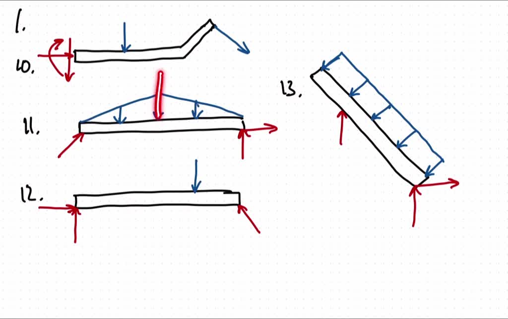
Solved Draw The Free Body Diagram For The Following Problems A The Cantilevered Beam In Prob 5 10 B The Beam In Prob 5 11 C The Beam In Prob 5 12 D The Beam In Prob
In this article Learn :cantilever beam Bending moment diagram B.M.D. and shear force diagram S.F.D. of a cantilever beam having point load at the end,several point loads,U.D.L. Over Whole Span ,U.D.L. not over the whole span,U.D.L. from support to some distance,U.D.L. Somewhere on the beam,Combination of Point Loads and U.D.L.

Shear Force And Bending Moment Diagram For Cantilever Beam With Three Point Load Civil Snapshot
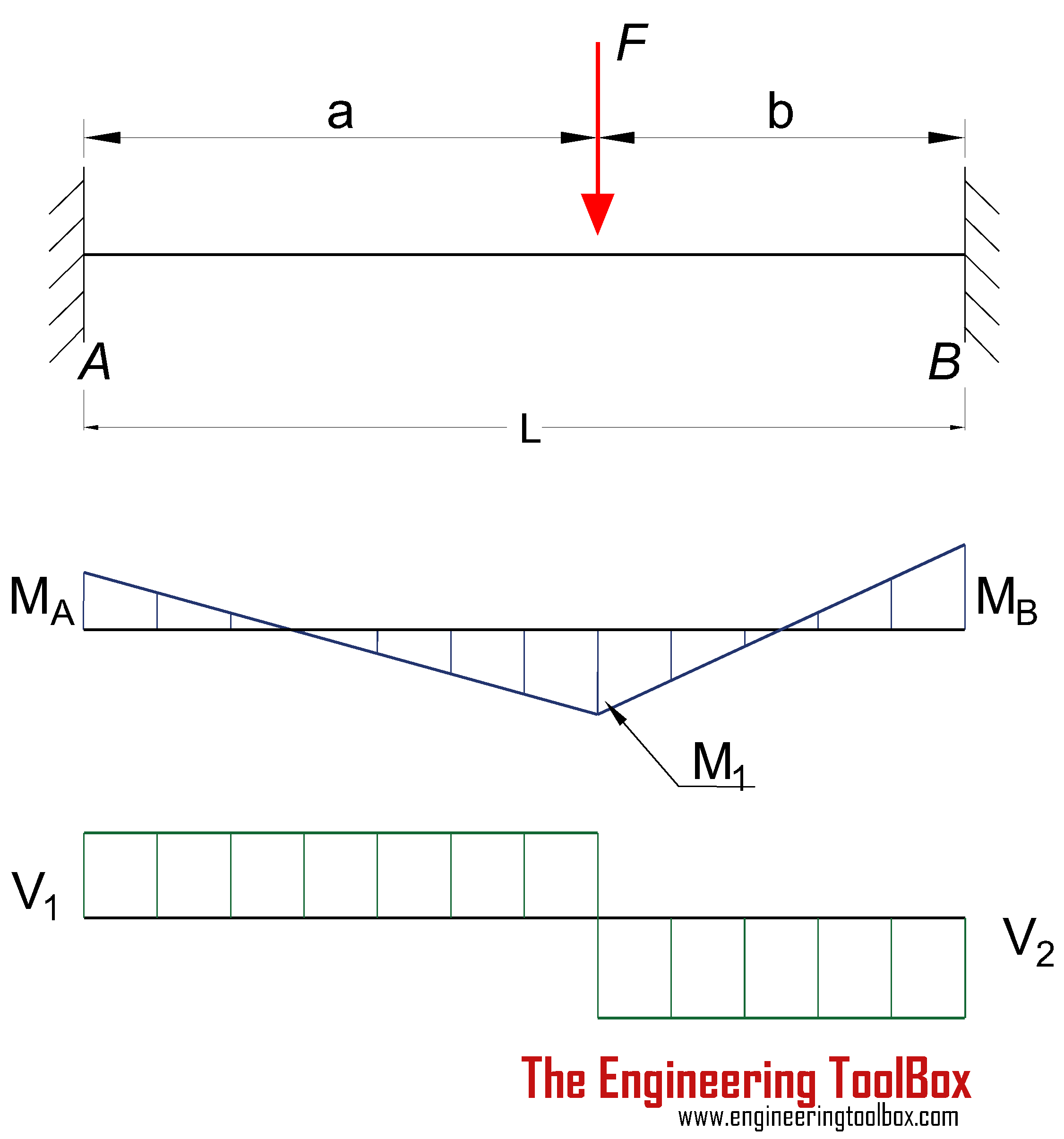
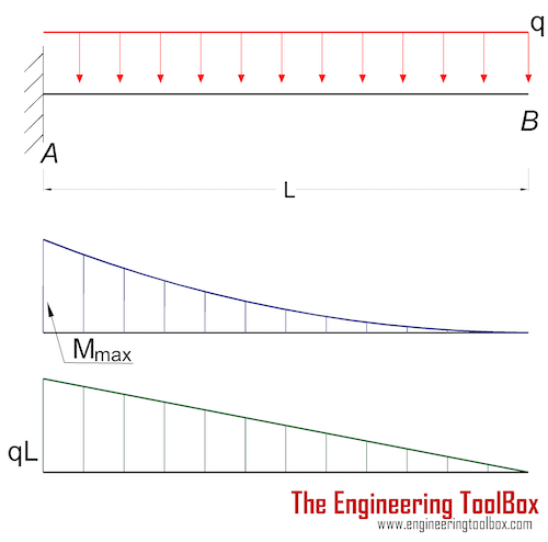
DIAGRAMS American Forest & Paper Association w R V V 2 2 Shear M max Moment x DESIGN AID No. 6. AMERICAN WOOD COUNCIL ... Figure 13 Cantilever Beam-Concentrated Load at Free End Figure 14 Cantilever Beam-Concentrated Load at Any Point. AMERICAN FOREST & PAPER ASSOCIATION R 1 R 2 V 1
Analisa Struktur 4 Apa Yang Dimaksud Free Body Diagrams
Another example is in a log splitter where the cylinder is pressing (applying load) at the same fixed distance away from the beam axis. The load applied by the cylinder creates a constant moment along the entire length of the beam. Once you have your loads, create a free body diagram showing each load and where it occurs on the beam.
Solved Problem 5 1 Vectors Fa Bx By Part A Draw The Chegg Com
Using the free-body diagram of the portion AC of the beam (Fig. 8.8), where C is located at a distance x from end A, we find (8.7) Substituting for M into Eq.. (8.4) and multiplying both members by the constant El, we write d 29' El Integrating in F, we obtain The deflection and slope at A are obtained by letting — O in Eqs. (8.11) and (8.9).
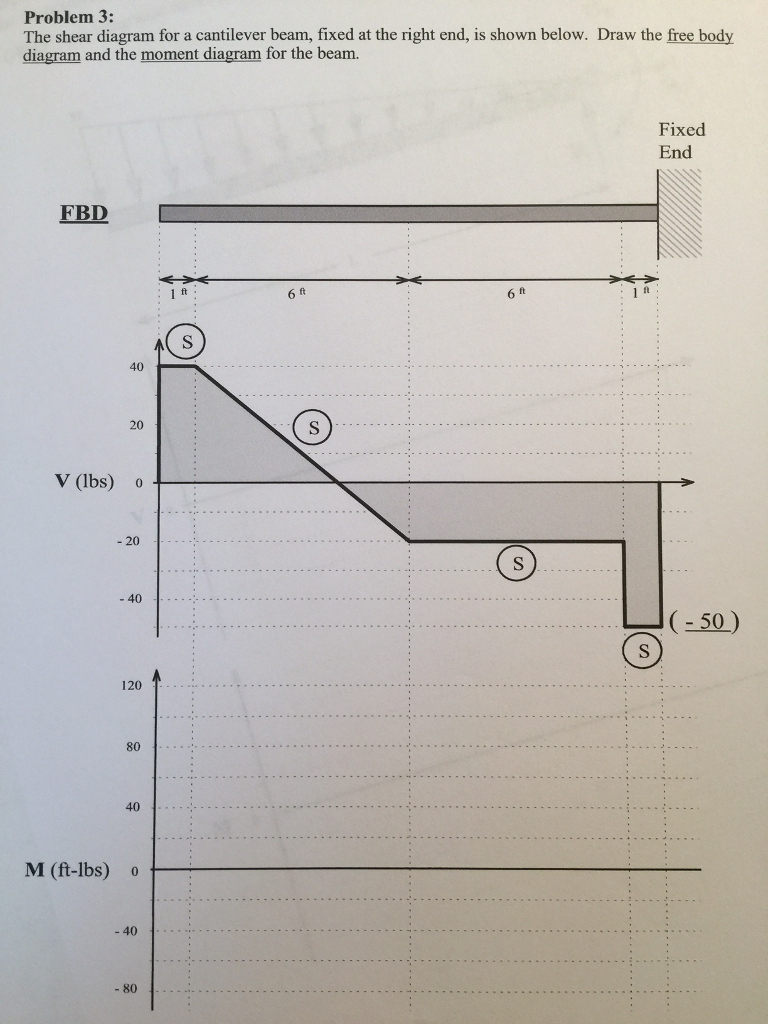
Solved The Shear Diagram For A Cantilever Beam Fixed At The Chegg Com
beam diagrams and formulas by waterman 55 1. simple beam-uniformly distributed load 2. simple beam-load increasing uniformly to one end ... 22. cantilever beam-concentrated load at free end. 23. beam fixed at one end, free to deflect vertically but not rotate at other-concentrated load at deflected end 24. beam overhanging one support-uniformly ...
1 4 Internal Forces In Beams And Frames Engineering Libretexts
A short video to show how to form an imaginary cut and draw a free body diagram of a simply supported beam with a point load.Related videos:Reactions of a Si...

Solved Example 6 For The Cantilever Beam Loaded As Shown A Chegg Com
Cantilever Beam Free Body diagram; Cantilever Beam Boundary conditions; Determine the internal shear and Bending moment in the cantilevered beam as a function of x; Finding Shear force and Bending Moment acting at a distance of 2 m from the free end on a Cantilever beam with Uniformly Distributed load (U.D.L.)
Beams Fixed At Both Ends Continuous And Point Loads
The stress in a bending beam can be expressed as. σ = y M / I (1d) where. σ = stress (Pa (N/m2), N/mm2, psi) y = distance to point from neutral axis (m, mm, in) M = bending moment (Nm, lb in) I = moment of Inertia (m4, mm4, in4) The maximum moment in a cantilever beam is at the fixed point and the maximum stress can be calculated by combining ...
Example 6
Free Body Diagrams. A free body diagram is a tool used to solve engineering mechanics problems. As the name suggests, the purpose of the diagram is to "free" the body from all other objects and surfaces around it so that it can be studied in isolation. ... 100 lb cantilever beam. Assume the beam is firmly anchored to the wall. Draw a free body ...

Figure A 2 Free Body Diagram Of End Loaded Cantilever Beam Showing Download Scientific Diagram
The cantilever is a beam which has one end free and the other is fixed. The following is the process for determining the reaction at the wall for a cantilever beam. And we have 14 inches from the point a to the right hand side. Cantilever beam free body diagram. At the ends of a simply supported beam the shear force is zero.

Draw Bending Moment Shear Force Diagrams Cantilever Beam Youtube
Figure-3: Bending and Shear Force Diagram of Cantilever Beam with Point Load at Free End The shear force at the fixed support A is determined by keeping the section at A, which gives the shear force Ra=W; and moment Ma = W.l. based on which the shear force and bending moment diagram are developed.

Shear Force And Bending Moment Diagram For Cantilever Beam Civil Snapshot
The above beam design and deflection equations may be used with both imperial and metric units. As with all calculations/formulas care must be taken to keep consistent units throughout with examples of units which should be adopted listed below: Notation. FBD = free body diagram; SFD = shear force diagram; BMD = bending moment diagram

Free Body Diagram For An Increment Of A Cantilever Beam Download Scientific Diagram
Draw the free body diagram for the cantilevered beam. If a beam is cantilevered it has a fixed support at one end which is the right end for this beam the beam weighs 150 lbft and the weight of the beam acts through its centroid. The wall holds the cantilever beam. All the reaction components will be experienced only on the fixed end.

Subhankar 4 Students S F D For Cantilever Beams
Web Ncyu Edu Tw
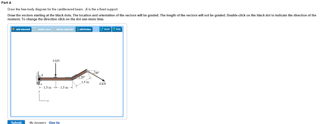
Solved Part A Draw The Free Body Diagram For The Chegg Com
Cantilever Beam Bearing Reactions Pickedshares

Bending Moment In A Cantilever Beam Physics Stack Exchange
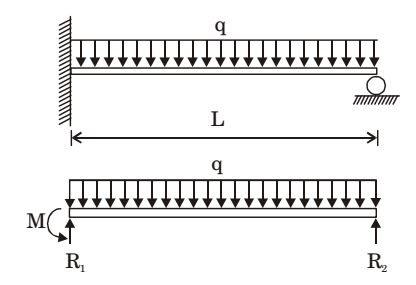
A Uniformly Loaded Propped Cantilever Beam And Its Free
Determining The Shear Force And Bending Moment Equations Of Cantilever Beam

Shear Force And Bending Moment Diagram Mechanicalstuff4u
4 3 Determinate Beam Analysis Learn About Structures
Cantilever Beams Moments And Deflections
Beam Analysis Validation Mechanicalc

Eng2000 Chapter 7 Beams Ppt Video Online Download
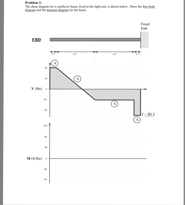
Solved Problem 3 The Shear Diagram For A Cantilever Beam Chegg Com

Everything You Should Know About Cantilever Beams The Constructor

The Cantilever Beam Model With Both A Parallel And Diagonal Cable Force Download Scientific Diagram

Shear Force And Bending Moment Diagram For Cantilever Beam With Point Load Civil Snapshot

Solved Determine The Force And Moment Reactions At The Support A Of The 1 Answer Transtutors
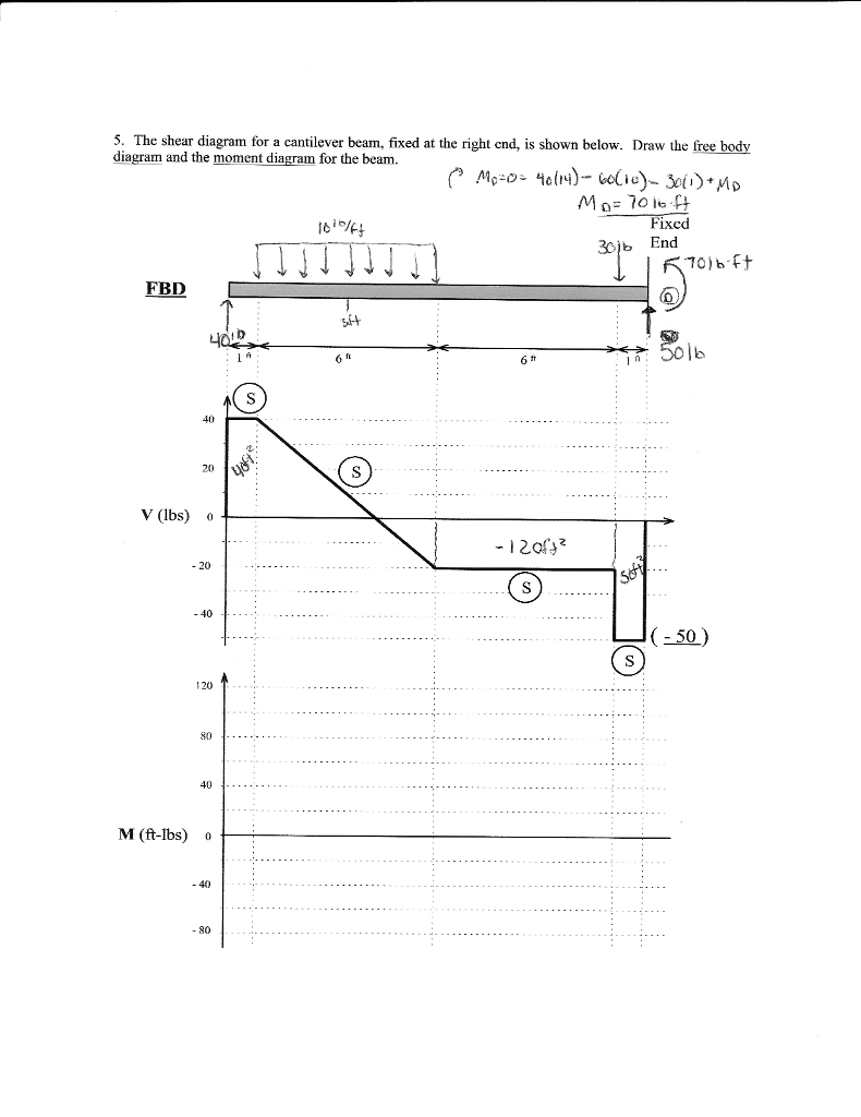
Solved 5 The Shear Diagram For A Cantilever Beam Fixed At Chegg Com
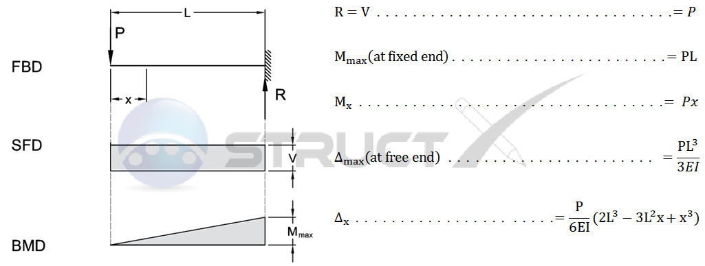
Cantilever Beam Point Load At Free End
Example 2

Shear Force And Bending Moment Diagram For Cantilever Beam Civil Snapshot

Statics Ebook Shear And Moment Diagrams Ii

A A Cantilever Under A Concentrated Load And B The Free Body Download Scientific Diagram

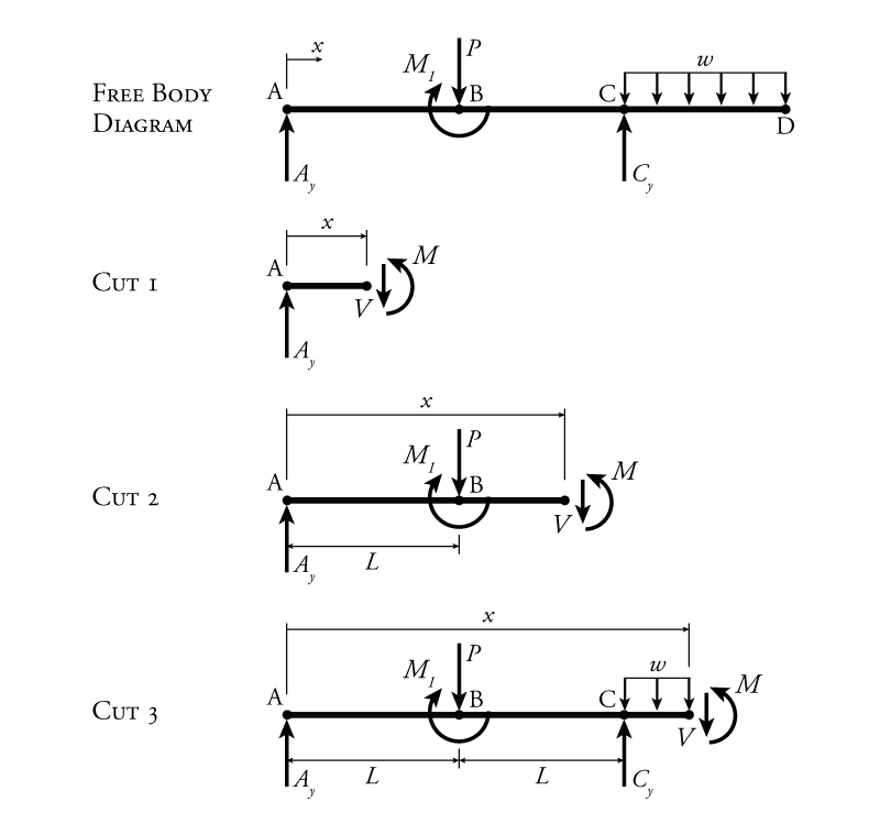
Free Body Diagram Of The Three Segments Of The Cantilever Beam Download Scientific Diagram
Examples On Equilibrium Problem1 Calculate The Tension T

Figure A 1 Free Body Diagram Of End Loaded Cantilever Beam Showing Download Scientific Diagram

Free Body Diagram Of The Three Segments Of The Cantilever Beam Download Scientific Diagram
0 Response to "41 cantilever beam free body diagram"
Post a Comment