45 jockey pump piping diagram
› faqsFrequently Asked Questions (FAQs) - New Age Caravans Tasmania Ensure that the pump is on or mains water is connected. In the caravan a switch with a red light can be found (most commonly found near the fuse box). This is the hot water service gas igniting switch Flick this on when you are ready to turn on the hot water service, the red light will illuminate when the gas is starting up. What Are Jockey Pumps and How Do They Work ... - Flow Tech ... A jockey pump, also known as a pressure-maintenance pump, is a small apparatus that works together with a fire pump as part of a fire-protection sprinkler system. It is designed to keep the pressure in the system elevated to a specific level when the system is not in use, so that the fire pump doesn't have to run all the time and the system ...
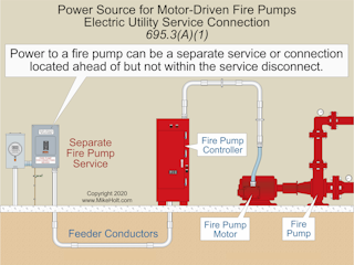
Fire and Jockey Pump Controller Sensing Lines including jockey pumps, shall be made between that pump's discharge check valve and discharge control valve. 4.30.3 The pressure-sensing line shall be brass, copper, or
Jockey pump piping diagram
› 25604132 › STORAGE_AND_HANDLINGSTORAGE AND HANDLING OF PETROLEUM PRODUCTS AT ... - Academia.edu storage and handling of petroleum products at depots and terminals prepared by functional committee oil industry safety directorate government of india ministry of ... PDF MASTER Master Model JPCE, Jockey Pump Controllers, are used in installations designed to NFPA-20, Standard for the Installation of Stationary Fire Pumps for Fire Protection. They are designed to maintain the system pressure so the fire pump does not start due to small leaks in the system. The Facts About Jockey Pumps | 2002-03-28 | PM Engineer Hence the name "jockey pump." The purpose of a jockey pump is to maintain pressure in a fire protection piping system so the larger fire pump does not need to run. A jockey pump package consists of a pump, motor and controller. Two Types of Pumps. There are two types of pumps available for jockey pump applications.
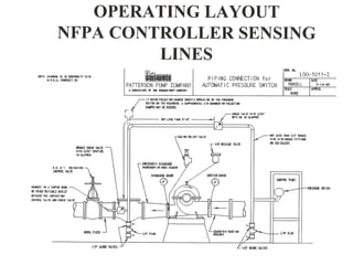
Jockey pump piping diagram. PDF Patterson Pump Company STANDARD JOCKEY PUMP CONTROLLER NEMA TYPE 3R ENCLOSURE A TYPICAL STANDARD JOCKEY PUMP CONTROLLER ELECTRICAL SCHEMATIC PS1 L2A/N 0.33 - 2 240/1/60 (1) #14 AWG (1) [2 MM SQ.] HAND OF F AUT O Patterson Jockey Pump Control Panel Model No. Voltage H.P. Rating Serial No. Encl. Type FLA. A SUBSIDIARY OF THE GORMANN-RUPP COMPANY MADE in U.S.A. 12.01 PDF Instruction Bulletin - Fire Pump Sales & Services Piping 5 Setting the Pressure Switch 6 ... The controller is intended to be mounted to a wall or a welded structure that is part of the pump package. Refer to the Outline Diagram for mounting hole sizes and locations. If the controller is ... The jockey pump controller has a Hand-Off-Auto selector switch on the right hand side of the Piping arrangements for fire pumps - Specifying Engineer Jockey pumps mitigate false alarms by compensating for small pressure fluctuations in system piping and return the system to its normal static pressure range under non-fire conditions. As with a fire pump, the jockey pump installation will include a controller with a pressure switch. Fire Water Pump Technical Requirement - PAKTECHPOINT Pump Technical Requirement for Fire Water Pump Skids. 1 Unless otherwise specified, the main and standby fire water pumps shall be double suction, horizontal split case design that allows access to the impeller without disconnecting the inlet and/or outlet piping or affecting alignment.The main fire water pump shall be motor driven and the standby fire water pump shall be driven by a diesel ...
PDF Fire Pump Systems in NFPA 20 Standard - controljo.com Fire Booster Flow Diagram in NFPA 20 1. Pump (Diesel Pump) 2. Pump SUCTION COLLECTOR WATER STORAGE TANK Rising Stem Valve with Monitoring Switch Check Valve Pump Butterfly Valve with Monitoring Switch Flow Meter Waste Cone Relief Valve DELIVERY COLLECTOR Jockey Pump. 12 ETNA Group Code Norm YN - NFPA 20 Pump Nominal Diameter (mm) Pump Impeller ... Jockey pump in fire system - Grundfos A jockey pump is a small pump connected to a fire sprinkler system to maintain pressure in the sprinkler pipes. This is to ensure that if a fire-sprinkler is activated, there will be a pressure drop, which will be sensed by the fire pumps automatic controller, which will cause the fire pump to start. Fire Pump Controller Drawings - Master Control S JPCV and PMCVE Drawings. Dimensionals. 10605 - JPCV: NEMA 2, Variable Speed Jockey Pump Controller. 24180 - PMCVE: NEMA 2,12 Variable Speed Pressure Mainenance Controller. External Wiring. 10604 - JPCV: Three Phase Variable Speed Jockey Pump Controller. PDF General Information Fire Pump Controllers & Jockey Pump ... facilitate isolation of the jockey pump controller (and sensing line) for maintenance without having to drain the entire system. [See Figures A-7-5.2.1 (a) and (b).] A-7.5.2.1(e) The pressure recorder should be able to record a pressure at least 150 percent of the pump discharge pressure under no-flow conditions.
PDF PJPC Jockey Pump Controller - Peerless Pump Figure A-10-5.2.1(a) Piping connection for each automatic pressure switch (for fire pump and jockey pumps). If water is clean, ground-face unions with non-corrosive diaphragms drilled for 3/32-in. orifices can be used in PDF The Jockey Pump, an Important Part of a Fire Pump System. The Jockey Pump, an Important Part of a Fire Pump System. August 1, 2009 Rev. No. 2 A Jockey Pump is an important component of a fire pump system. The Jockey ... Choosing a PMP for an interior piping system, supplied by a fire pump system taking suction directly from a water supply without any underground, is a very NFPA 20: Fire pump design - Consulting-Specifying Engineer H orizontal split case pumps are only permitted to have elbows and tees installed perpendicular to the pump when the fitting is located at least 10 pipe s ize diameters from the suction flange (NFPA 20-2013, Section s 4.14.6.3.1 to 4.14.6.3.3). law.resource.org › pub › inDESIGN AND INSTALLATION OF FIXED ... - Public.Resource.Org Jockey Pump—A small pump used to replenish minor water loss to avoid starting an automatic suction or booster pump unnecessarily. 3.31. Low-Rise System—A sprinkler system in which the highest sprinkler is not more than 45 m above ground level or the sprinkler pumps. 3.32. Main Distribution Pipe—A pipe feeding a distribution pipe. 3.33
Fire Pump Systems | EC&M
Diagrams --Typical Pump Installations - Water Pump Supply Diagrams --Typical Pump Installations. The information provided here is for educational purposes only. Technically qualified personnel should install pumps and motors. We recommend that a licensed contractor install all new systems and replace existing pumps and motors. Failure to install in compliance with local and national codes and ...

Examples of Proper Fire Pump Equipment Installations | Steven ...
Jockey Pump Piping Diagram Jockey Pump Piping Diagram A jockey pump is a small pump connected to a fire sprinkler system and is intended to maintain pressure in a fire protection piping. Questions about the orifice checks in the SENSING LINES has come up quiet often. The above capture is an age-old drawing covering sensing lines for a jockey pump and fire pump controller.

Pressure sensing Line in a Fire Fighting Pump Room-Malayalam
Installing Sensing Lines in Jockey and Fire Pump Systems The first part is understanding that the jockey pump and the fire pump need to be located on the high-pressure side of the fire pump piping. Generally, the layout will be the pump suction or inlet, the pump discharge or outlet, and then you must pipe onto the fire pump discharge piping a ¾ "casing relief valve.
Odlučovače tuku ACO LipuSmart-P včetně čerpacího zařízení
PDF User's Manual - Pump Manufacturing Lag pump stops after the lag stop pressure is achieved and the flow rate is lower than the flow start setting for the off-delay time period. When all lag pumps are stopped, the jockey pump will restart and if the pressure is still being maintained, the pump will shut down after the off -time delay.

Relief Valves for Centrifugal Pumps According to NFPA 20 ...
Каталог запчастей на спецтехнику С помощью электронного каталога на импортную спецтехнику, представленного на этом сайте, вы можете определить оригинальные номера (oem) запчастей вашей техники, узнать их цену и цену аналогов в интернет-магазине ...
304-2437 Brandschutz EN RZ:Layout 1
PDF General Information Typical Pressure Sensing Line ... between the pump discharge flange and the discharge control valve, as appropriate. A.10.5.2.1 Installation of the pressure-sensing line between the discharge check valve and the control valve is necessary to facilitate isolation of the jockey pump controller (and sensing line) for maintenance without having to drain the entire system (See figure

Piping Layout for Centrifugal Pumps
pngrb.gov.in › OurRegulation › ppp-GSR-InfraWelcome to Petroleum and Natural Gas Regulatory Board ... - PNGRB 7.12.2 Motor driven Jockey pump shall be installed to pressurize fire water network as per design requirement. 7.12.3 The fire water pumps including the standby pumps shall preferably be diesel driven. Where electric supply is reliable 50% of the pumps may be motor driven.

Mi3 Pump & Motor Trading - Home | Facebook
PDF Fire Pump Package Pumping Systems - Xylem Inc. 2.4.3 Refer to fire pump panel and jockey pump panel wiring diagrams for additional switch/alarm connections. 2.5 MISCELLANEOUS CONNECTIONS 2.5.1 Certain items are shipped loose and are intended to be field installed. Items that may be shipped loose are: hose header and valves, muffler, 10ft fuel tank vent pipe, ball drip valve. If applicable

Fire Water Pump Technical Requirement | PAKTECHPOINT
PDF INSTALLATION AND OPERATION INSTRUCTIONS Jockey Pump ... Firetrol Jockey Pump Controllers are listed by Underwriters' Laboratories, Inc., in accor- ... piping procedure of the sensing line between the pumping system and the controller. ... consult the appropriate field connection diagram included with the manual. For proper wire sizing, refer to the National Electrical Code, NFPA 70.
System Electric Diesel Jockey Pump Pressure Tank Fire Pump ...
Typical Configuration of Pump in Piping and ... Typical Configuration of Pump on PID. Figure above reprsents typical piping and instrumentation diagram of pump. Pump should have: Pump Symbol. Make sure you use proper pump symbol. As for example above, I use centrifugal pump. Check your P&ID legend. All the nozzles should be correctly represented with size and flanges.

Desolate Continent Inspect jockey pump pressure setting ...
PDF QUICK RESPONSE Fire Pumps - Sensing Lines.doc - pdfMachine ... D = Jockey Pump Controller C D A B January 2009 From Supply To System F E FIRE PUMPS ΠSENSING LINES Most commonly the pump controller is connected to the fire protection system by means of piping know as a sensing or pilot line. Each pump, including the jockey pump, shall have its own individual

Consulting - Specifying Engineer | Understanding fire pumps ...
echte-freude-schenken.de › fire-nozzle-gpm-chartFire nozzle gpm chart - echte-freude-schenken.de Mar 11, 2022 · Fire nozzle gpm chart. email protected] [email protected] [email protected]
RESPONSE QUICK
Fire Pump Installation Inspection Checklist.pdf Fire pump and controller, piping, gauges, jockey pump, and other component locations and design are the same as shown on the approved set of plans. 8. Fire pump has name plate. 9. Wire installation to motor, control inner wiring, and jockey pump wiring is correct. 10. A pressure gauge not less than 3 ½ in. diameter is near the pump discharge ...

Standard NFPA20 Industrial Trading è in grado di fornire gruppi ...
What is a Jockey Pump? (with pictures) - Info Bloom The Jockey pump is fitted with a pressure switch, which will cut in a cut off time. The jockey pump won't start unless there is a leak and the pressure in the pipe line decrease. While the pressure decreases, the cut in pressure is reached and the motor starts. When the required pressure reaches the cut off pressure, then the motor stops.
![nfpa 20 presentation - [PDF Document]](https://static.fdocuments.in/img/1200x630/reader025/reader/2021042921/54514918af795915308b465e/r-1.jpg?t=1.1.9)
nfpa 20 presentation - [PDF Document]
Jockey Pump Requirements & Sizing - NFPA 20 - Fire ... 1- For situations where the jockey pump serves only above ground piping for fire sprinkler and standpipe systems: The jockey pump should be sized to provide a flow less than a single fire sprinkler. The main fire pump should start and run (providing a pump running signal) for any water flow situation where a sprinkler has opened, which will not ...

ACSE.CO.,LTD - Pressure sensing piping line connection for ...
PDF QUICK RESPONSE Fire Pumps - Jockey Pump.doc - pdfMachine ... A jockey pump, also know as a pressure maintenance pump, maintains the pressure in the fire sprinkler system to avoid non-emergency starting of the main fire pump. This keeps the main fire pump from short cycling, which shortens its life span. The jockey pump is designed to start before

Jockey Pump Sizing | Prosafe-HSE-Safety Engineering
PDF DO NOT SCALE - Geared Projects jockey pump pressure cell 1500kpa annubar (provision only) flow indicator Ø80 ... tank & pumpset piping & instrumentation diagram not to scale existing 400kl tank nc nc existing tank water make-up system no ... overflow piping to suit tank & pump manufacturers requirements & local equipment layout. provide galv. steel pipe supports to suit.

Firewater System - an overview | ScienceDirect Topics
oilgascourse.com › ogc › our-courses-a-zOur Courses A-Z | DEVELOP Piping Instrument Diagram/PID&Process Instrument Control untuk Projects&Plant Operation Training Piping Integrity Fit for Service Assessment Training Piping Line Sizing,Material Specification&Material Take Off Engineer Training
Fire Pump Design Calculate Appilcation For Andriod
The Facts About Jockey Pumps | 2002-03-28 | PM Engineer Hence the name "jockey pump." The purpose of a jockey pump is to maintain pressure in a fire protection piping system so the larger fire pump does not need to run. A jockey pump package consists of a pump, motor and controller. Two Types of Pumps. There are two types of pumps available for jockey pump applications.

Fw pump basis nfpa
PDF MASTER Master Model JPCE, Jockey Pump Controllers, are used in installations designed to NFPA-20, Standard for the Installation of Stationary Fire Pumps for Fire Protection. They are designed to maintain the system pressure so the fire pump does not start due to small leaks in the system.

PDJ Series Fire Fighting Set With Diesel Pump And Jockey Pump ...
› 25604132 › STORAGE_AND_HANDLINGSTORAGE AND HANDLING OF PETROLEUM PRODUCTS AT ... - Academia.edu storage and handling of petroleum products at depots and terminals prepared by functional committee oil industry safety directorate government of india ministry of ...
Jockey pump fire pump, Industrial fire extinguishing system ...

Electric Jockey Pump with Diesel Fire Pump System (PEDJ 50Hz ...
Installation and Operation Instructions

Pin on Meal plan
Fire Pump Systems | EC&M

Fire pumps sensing line - Fire Protection Specialists

Other Systems - AE 390- Assignment 7
Fire group equipped with horizontal pump + jockey pump

3D Fire Pump Room (Revit Mep) | Fire fighting pumps ...

Fire Pump Room

Jockey Pump Requirements & Sizing - NFPA 20 - Fire Protection ...
INSTALLATION AND OPERATING INSTRUCTIONS VERTICAL IN-LINE FIRE ...
Fire Protection Vertical In-Line Pumps - Empowering Pumps and ...

Fire Water Pump Station Design, Piping Instrumentation ...

Fire pump settings - NFPA 20 - Fire Protection Specialists
Fire pumps
Desolate Continent Inspect jockey pump pressure setting ...
Aurora Packaged Fire Pump Systems - Fox Valley Fire & Safety
Fire Pump System

Piping and instrumentation Diagram | Chemical Engineering Portal
NFPA Inspection Requirements for Fire Pumps in Commercial ...

MEP WORK - fire sprinkler system | Facebook

ATV600 - Jockey Pump Control Introduction
NFPA 20: Changes to the fire pump standard: Regardless of ...
0 Response to "45 jockey pump piping diagram"
Post a Comment