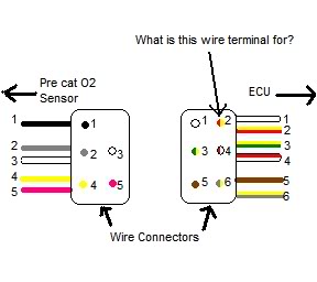
44 5 wire o2 sensor wiring diagram
E46 325i oxygen sensor diagram | E46 Fanatics Forum I've used all my old sensors and wiring which had absolutely no issues at all. The conclusion I've come up with is that when plugging the O2 sensors back into the loom I may have miss matched them as I didn't label them. Does anyone have a diagram of which sensor plugs into where on the loom ?
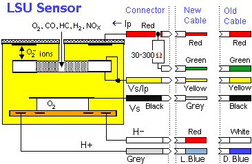
Wideband O2 Sensors and Air/Fuel (A/F) Sensors Wideband 2 sensors typically have 5 wires while most A/F sensors have 4 wires. Another way to check the output of a wideband O2 sensor or A/F sensor is to connect a digital voltmeter or graphing multimeter in series with the sensor's voltage reference line (refer to a wiring diagram for the proper...
5 wire o2 sensor wiring diagram
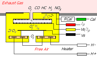
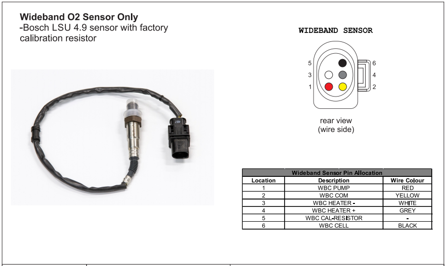
Oxygen sensor - Wikipedia The wiring diagram for the wideband sensor typically has six wires: resistive heating element, resistive heating element, sensor, pump, calibration resistor, common. Titania sensor. A less common type of narrow-band lambda sensor has a ceramic element made of titania (titanium dioxide). This type does not generate its own voltage, but changes its electrical resistance in … Wiring and Sensors | Ignition Output (MS-II) Note that the external wiring diagram in this Sensors and Wiring section is entirely separate from, though similar to, the Relay Board. The difference between the heated (3 or 4 wire) O2 sensor and a non-heated (one wire) sensor is the A/F ratio sensing of warm up and low load conditions. SOLVED: 2001 Cadillac Deville oxygen sensor wiring diagram - Fixya Why do you need a wiring diagram for a O2 Sensor? 2001 Cadillac Deville Car Radio Wiring Diagram. Car Radio Battery Constant 12v+ Wire: Orange Car Radio Accessory Switched 12v+ Wire: Yellow Car Radio Ground Wire: Black Car Radio Illumination Wire: Gray Car Stereo Dimmer Wire...
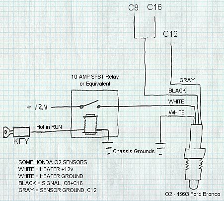
5 wire o2 sensor wiring diagram. Wiring and Sensors Wiring and Sensors. In order for your MegaSquirt to determine the amount of fuel to inject, you will need several functioning sensors For the O2 sensor, the wiring depends on the type (1, 3, & 4 wire) and make. There are some guidelines in this manual, and a lot of information in the archives. Rear O2 sensor bypass/CEL fix. | Page 5 | Tacoma World First off, the two diagrams are not wired the same. The first diagram does not remove the O2 sensor from the circuit. Snipped white and blue wires leading to the sensor were covered with heat shrink tube. I didn't pull any connection plug or the sensor out of the pipe,no real need because I had the... o2 sensor wiring - YotaTech Forums wire colours on the truck are as follows. black and double insulated. i assume this is the sensor (+) brown white w/ red stripe pink or brown w/ green stripe. In the "engine control", 3VZ section, page 62, is the wiring diagram for the oxygen sensors. Dodge RAM 1500 Questions - O2 SENSOR WIRING DIAGRAM I need to know the wiring diagram for the o2 sensor so I can wire in a narrow band air to fuel ratio gauge. There are 2 white wires, one black wire, and one grey wire. I know the 2 white ones are for the heater element, just not sure about the grey or black one. Any info can help thanks!
Oxygen sensor downstream wiring I have | EricTheCarGuy | Forum I have a black wire , grey wire, and 2 white wires. The way it is wired it shows on ohm meter it should be working but it is not. Is there a way to figure out You will need a wiring diagram for your specific vehicle. If you have a 4 wire O2 sensor and a 4 wire hook up from the engine harness, the lay out is... o2 sensor wiring | ZCar Forum The wire on my o2 sensor runs into the EFI harness on my '81 ZX Turbo. It appears to be black. I would look there first, then look to xenonS130 dot com. I have the fsm for 1980zx and it does refer to an exhaust gas sensor and it does have the same diagram that was previously posted. and the thing... LS Standalone Wiring Harness Diagram | General Installation • O2 sensors should always be installed as close to the engine as possible in order to allow for proper sensor heating and function. The further from the engine the sensors are installed the more time the sensors will take to heat up and put the engine in closed loop. HOW DO I HOOK UP MY AC REQUEST WIRE? • The AC Request Wire must be hooked up to a 12-volt source … Air/fuel ratio sensor testing thread... - SCANNERDANNER | Forum Wiring checks on these sensors are fantastically simple. Four wires, following the typical Bosch O2 sensor-side wire color format - the two wires colored alike are the heater circuit, the Like the Toyota sensor, this design makes it very easy to quickly verify circuit integrity, even without a wiring diagram.
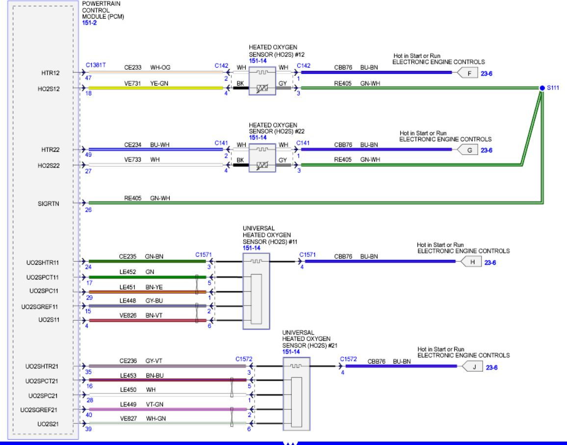
PDF T:\data\Liberty\Datasheets\DS00417-A EN13922 ROM 2305E 5-wire... 111OE Overfill Sensor. II. BLUE ORG. 5 'wire cnble EL04098. TITL£: ROM3205E 5-wire TOP SENSOR WIRING DIAGRAM CONFORM NEN-NE13922. Oxygen (O2) Sensor Wiring Diagrams (1997 4.6L F150-F250) The 4.6L Ford F150 and F250 Pickup comes equipped with 4 heated oxygen sensors (HO2S). This article contains the wiring diagrams of all 4 oxygen sensors. RF Oxygen Sensor (O2S11) Wiring Diagram. 2.9L MAF Conversion - Detailed Procedures - The Ranger Station 4.12 The 1990 wiring diagram shows the speed sensor connection at 6 is also grounded. You can form this ground by making a looping My 1986 had a 3 wire sensor. I think you need to form a wire jumper from 46 to 49 to enable a good HEGO signal return (if you have a 3 wire O2 sensor). P0641 Code: Sensor Reference Voltage "A" Circuit/Open - In ... 30.07.2021 · If the 5 volts feeding the three-wire sensors is shorted to ground, it pulls all the three-wire sensor voltages to zero, and on some vehicles (like Fords), it will put the PCM to sleep so that there is no spark, fuel injection, or communication with the scan tool; thus there is no DTC for a shorted 5 volt rail on a system where the ECM/PCM has just one 5 volt rail because the …
Part 1 -Front Oxygen Sensor Heater Tests (2002-2003 2.5L Nissan...) You can see these wires in the O2 sensor wiring diagram here: Heated Oxygen Sensor 1 Circuit Diagram. TEST 1: Making Sure The O2 Sensor The wire that carries these 12 Volts to the O2 sensor is the red with yellow stripe (RED/YEL) wire. We'll use a multimeter to check for these 12 Volts.
P0420 – Meaning, Causes, Symptoms, & Fixes 21.02.2022 · 4. 2 upstream O2 sensors & 1 downstream sensor. 5 . catalytic converter has been replaced twice All of this and the light is still on. Can some one please give me some advice on what to do now. I don’t know if it is part of it, but the evap code always comes on & won’t reset. Please help! Reply. Marshall says: 12 October, 2020 at 9:04 pm. Based on the instructions …
need help on universal oxygen sensor wiring | Toyota Nation Forum The wiring diagram for a 5SFE shows only a white wire for the main sensor. This would be for the O2 signal. However, newer ones came out with a The receptical wires for the two wire sensor are red and brown, however. Kep. Often, it's the loose screw between the steering wheel and the driver's seat...
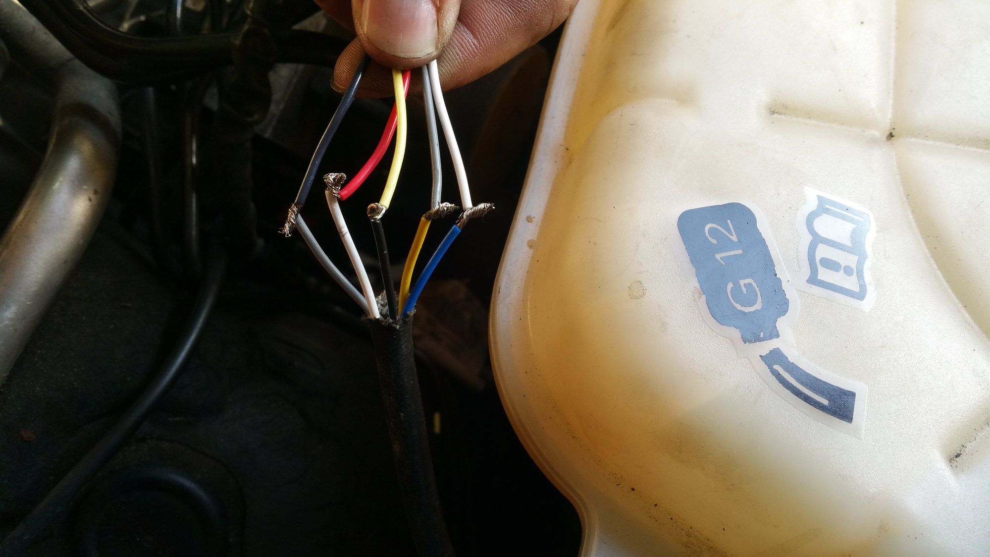
Reading 5-wire O2 wideband sensor? - Honda-Tech - Honda Forum... Which wires to use? First O2 sensor wires are: yellow orange red white black. Presumably two will give the voltage readout indicating amount of rich/lean? OK it's just that the wire diagrams that I have in my 96-00 Civic Honda Shop manual are showing 7. I didn't really check the diagram to see if they all came out...
4 wire oxygen sensor conversion - wiring diagram? | Pirate 4x4 The sensor I have is from an 87 truck, and has 4 wires on it... one blue, one white, and two black. I know that one of these is the actual signal to the ECU I beleive Bosch and NGK both ahve some O2 sensor wiring diagrams oin thier websites as they both offer some generic replacement O2 sensors.
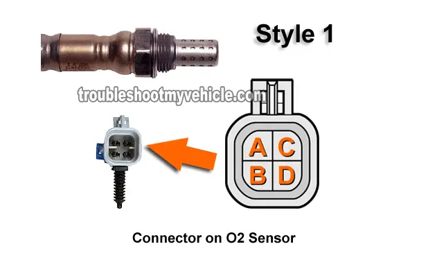
Oxygen Sensor: 1, 2, 3, 4 Wire O2 Sensor Wiring Diagram The wiring diagram of the oxygen sensor is different based on year, make, and model. It depends upon the manufacturer, how they design the wiring A one-wire oxygen sensor has one signal wire means a voltage wire, which goes to the car computer. These kinds of sensors are earthed via the...
GM O2 Sensor Wiring Diagram | ... about UNIVERSAL LAMBDA... Buy GLOBAL-AUTOMOTIVE, OXYGEN SENSOR WIRING DIAGRAM items on eBay. Find a huge selection of items and get what you want Our step by step walkthrough and wiring diagram showing you How To Convert OBD2 to OBD1 in your Honda or Acura SOHC or DOHC engines.
How 5-Wire Sensors Work (Tech Edge) When using a 5-wire (wideband) sensor we make certain assumptions about the environment the sensor is used in, for example we assume the sensor is It is possible to force a current through the molten electrolyte and to drive the chemical reaction such that oxygen is pumped (in the form of o2...
O2 sensor wiring diagram - Ford Truck Enthusiasts Forums Which wires go to my sensor wires? Any assistance would be greatly appreciated. Thank you. There is a movement on the sensor so I'm guessing it's not the wiring. My question is, is the brand new sensor broken, or is my catalytic convector dying (which is 3...
PDF Manual: 6888Xi Advanced Electronics for Zirconium Oxide Flue Gas... Multiple wiring diagrams are shown in this section. Always refer to the diagrams that apply to your transmitter configuration and disregard all other wiring diagrams. Sensor Type - O2 or CO 1. O2 - For Rosemount O2 probe models including Oxymitter and 6888, and most similar.
DIY installation of a 4-wire O2 Sensor for the '90 to '93 Miata. Heated (4-Wire) O2 sensors overcome this problem by including a 12V electric heating element (#8 in this diagram) within the sensor. These heating elements (typically 25W or so) keep the sensor heated to 1100°F or and therefore smack in the middle of it's optimal operating range.
Need help with O2 sensor wiring. - JeepForum.com The wire colors I have are: O2 Sensor (still in the plug) White White Black Grey. Body Plug (with all the wires pulled out) Black/Red Black/Tan Black/Blue Does your diagram show which wire goes where in the plug? Maybe I didn't make myself clear. My O2 sensor is now installed in the cat and the 4 wires are...
LC-2 Digital Air/Fuel Ratio (Lambda) Sensor Controller Manual Sensor Cable Connector – Mates the sensor cable to the O2 sensor. 3. Wiring – The LC-2’s wiring is very straight forward. All that is needed for basic installation is power (red) and ground (black). The two configurable analog output wires (one yellow and one brown) can be used to feed external Standalone ECUs, 3rd party data loggers, and AFR display gauges. 4. Serial IN & …
Oxygen Sensor Wiring Readings/Help | DODGE RAM FORUM Oxygen Sensor Wiring Readings/Help. Tags. 2005 efie o2 sensor ram 1500 wiring diagram. Hello Goose, Did you solve your problem? I currently have the same problem and cannot find twelve volts on any of the 02 sensor pins coming from the ecu.
Fuel Injection Systems & Parts - Jegs High Performance Shop for an aftermarket fuel injection system online at JEGS High Performance. We carry a large selection of performance fuel injection systems and fuel injection parts to help you increase horsepower and make repairs. Buy a fuel injection kit or get the exact aftermarket fuel injectors you need to get back on the road.
3 wire O2 sensor wiring. Help needed | Forum - NASIOC I was curious if someone could reference me a pic or wiring diagram so that I know in what order the wires connect. o2 sensor has 2 white and 1 black one. The other side of the connector has yellow, red and brown.
P2135 Code: Throttle/Pedal Position Sensor/Switch A/B ... 30.06.2021 · Think of this as “throttle by wire,” because there’s always an electronic module receiving input from the APP sensors, driving the motor that opens the throttle plate, and reading throttle plate position from the throttle position sensors. Redundant sensors are used on the accelerator pedal AND the throttle body as a solidly dependable way of detecting faults by …
o2 sensor wire colors - from the car | Jeep Garage - Jeep Forum So I have to replace upstream sensor 2/1 due to fault codes - upon investigation, the loom connector has been replaced with crimps and I want to ensure that Does anyone know the correct colors of the joining cables car side - or better still have a wiring diagram for the WK o2 sensors - looking around...
SOLVED: 2001 Cadillac Deville oxygen sensor wiring diagram - Fixya Why do you need a wiring diagram for a O2 Sensor? 2001 Cadillac Deville Car Radio Wiring Diagram. Car Radio Battery Constant 12v+ Wire: Orange Car Radio Accessory Switched 12v+ Wire: Yellow Car Radio Ground Wire: Black Car Radio Illumination Wire: Gray Car Stereo Dimmer Wire...
Wiring and Sensors | Ignition Output (MS-II) Note that the external wiring diagram in this Sensors and Wiring section is entirely separate from, though similar to, the Relay Board. The difference between the heated (3 or 4 wire) O2 sensor and a non-heated (one wire) sensor is the A/F ratio sensing of warm up and low load conditions.
Oxygen sensor - Wikipedia The wiring diagram for the wideband sensor typically has six wires: resistive heating element, resistive heating element, sensor, pump, calibration resistor, common. Titania sensor. A less common type of narrow-band lambda sensor has a ceramic element made of titania (titanium dioxide). This type does not generate its own voltage, but changes its electrical resistance in …











0 Response to "44 5 wire o2 sensor wiring diagram"
Post a Comment