43 emg wiring diagram solder
N. Korea's parliamentary session | Yonhap News Agency 2021-09-30 · N. Korea's parliamentary session. This photo, released by North Korea's official Korean Central News Agency on Sept. 30, 2021, shows Kim Yo-jong, North Korean leader Kim Jong-un's sister and currently vice department director of the ruling Workers' Party's Central Committee, who was elected as a member of the State Affairs Commission, the country's … Original Emg Wiring Diagram Solder Jackson slsmg emg wiring-diagram emg wiring harness diagram zakk wylde Easy No Soldering Emg 81 85 Pickup Installation Zakk Wylde wiring diagram inspirational zakk wylde guitar original emg wiring diagram luxury. They have the specs for every pickup, wiring diagrams and lots of other stuff.
Older EMG DG20 wiring help | Fender Stratocaster Guitar Forum Hi, I purchased second hand an older version of the EMG DG20 loaded pickguard that has the SPC and EXG controls. I know its an older model because its not prewired. I google'd and search everywhere for wiring diagrams and I'm at a loss. Attached is a pic of the back of the pickguard. It shows only 2 wires.
Emg wiring diagram solder
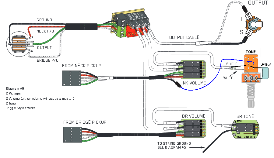
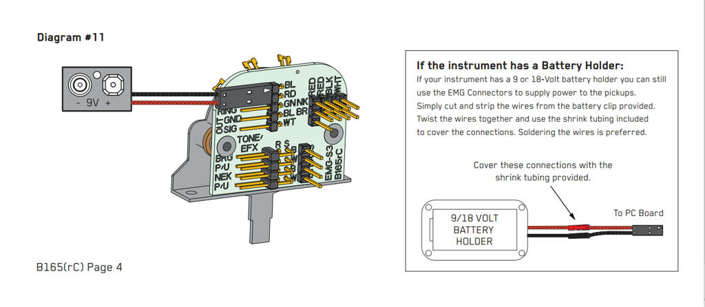
PDF Emg Mmcs Wiring Diagram - Preamps | Bartolini | Aguilar Diagram #8 1 3 Soldering to the battery buss: If your instrument has an older EMG Pickup you can solder the pickup RED wire to the buss. Simply use some needle nose pliers, pull out the V+ header and solder the RED Wire from the pickup(s) to any of the pins and then re-insert the header into the housing. 2 +18 Volt Wiring Option: PDF Installation Information Emg Models: T & Tc Sets EMG Models: T & TC SET OUTPUT JACK T R S BOTTOM VIEW Mounting the Controls: Refer to Diagram #5 1) Remove the existing controls from the control plate and mount the EMG controls as shown to the right. Be sure the PC Board on the switch is facing the same direction as the diagram shows. Diagram #5 Plug in the Pickups: Refer to Diagram #6 Humbucker Series/Parallel - GuitarElectronics.com This guitar wiring modification shows how to use a two position double pole-double throw On/On mini switch or a standard push/pull pot to select series or parallel modes. In humbucker mode, the output will be strong with a smooth attack and a deep tone. In parallel mode, the sound will be very clean and sparkly with lower output. Note: Both ...
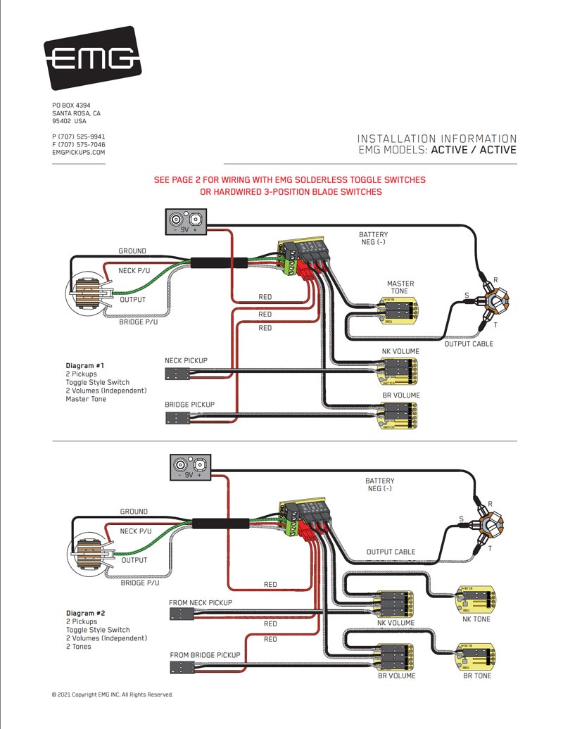
Emg wiring diagram solder. Original Emg Wiring Diagram Solder - schematron.org 11.09.2018 11.09.2018 4 Comments on Original Emg Wiring Diagram Solder At first I wired per EMGs diagram but it was looping the signal back I eventually got frustrated and had to solder everything. I guess a better way to ask the question is if EMG can either provide instructions or post a schematic how they Please let us know if you have any ... PDF Installation Information Emg Models: H3, H3a, H4, H4a EMG-HZ Wire Order: Pin 1 Green (GRN) Pin 2 White (WHT) Pin 3 Braid (GND) Pin 4 Red (RED) Pin 5 Black (BLK) 1) Plug the pickup cable onto the EMG Pickup header as shown in Diagram #1 and route the cable to the control cavity. If the cable is too long, wind up the excess and keep it under the pickup or in the control cavity if possible. PDF GZR PJHZ Instructions 0230-0281rF If your guitar is wired in the same fashion, simply follow the diagram and install the cables as shown. 3) If your instrument has a selection switch or the wiring is different, vist our website; emgpickups.com for more diagrams and video installations. PJ-HZ GZR SET Page 2 Installation Instructions: EMG Models: PJ-HZ GZR SET Diagram #1 PDF INSTALLATION INFORMATION EMG Models: EMG-89, 81TW ... diagram and route the cable to the control cavity. 4) Solder the braid of the pickup cable to the case of the volume control as shown in the diagram and connect the switch wires as shown. 5) For two-pickup guitars, follow steps 1-4 before continuing. 6) Remove the existing output jack and replace it with the EMG output jack. Solder the output ...
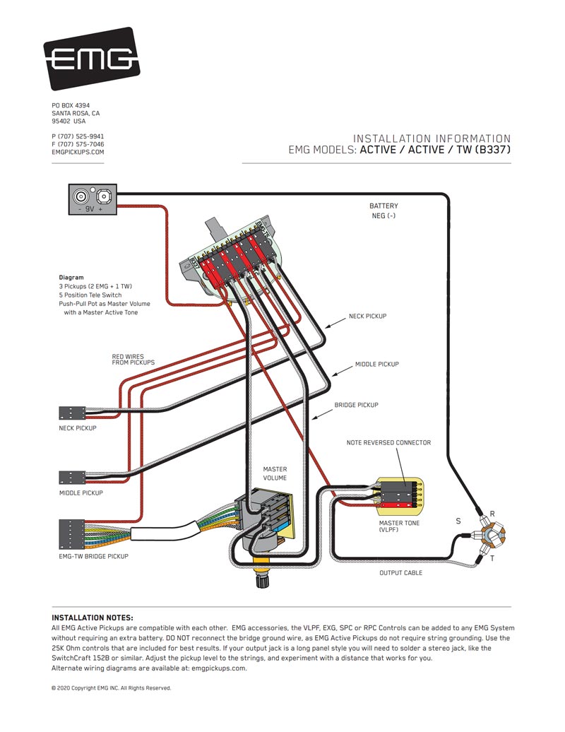
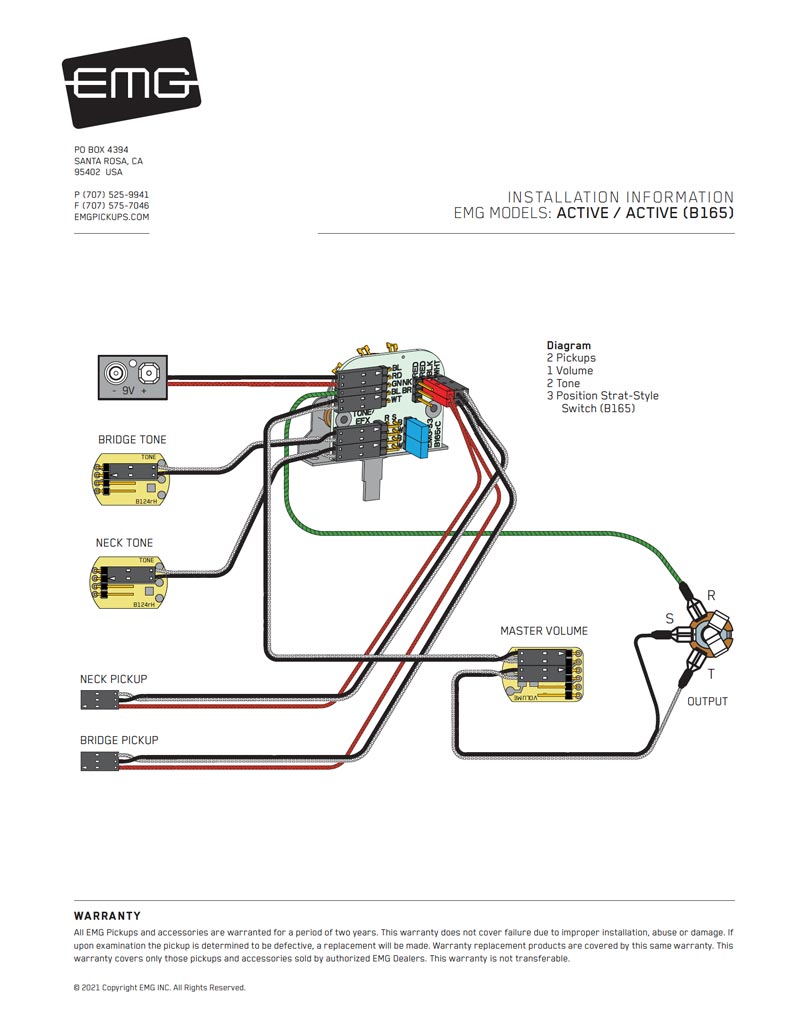
Emg Wiring Diagram Solder - The Wiring Jan 16, 2022 · Emg 81 85 wiring diagram wiring diagrams emg 81 wiring diagram as well as emg wiring diagram solder furthermore emg hz wiring diagram additionally emg. The 81 pickup is usually placed in the bridge position, where it produces a crisp distorted tone, and the 85 pickup is placed in the neck position, where it can produce smooth and saturated tones. Emg Solder Wiring Diagram - The Wiring Jan 14, 2022 · For EMG pickups, the white wire is the signal output and the metal braid is the ground for the signal and power. Original Emg Wiring Diagram Solder. If you or anyone has any EMG/active wiring questions, please feel free to ask me. 21 Pictures Of Emg 81 85 Wiring Diagram solder. PDF Emg Jx Set Wiring Diagram - Preamps | Bartolini | Aguilar Diagram #5 1 3 Soldering to the battery buss: If your instrument has an older EMG Pickup you can solder the pickup RED wire to the buss. Simply use some needle nose pliers, pull out the V+ header and solder the RED Wire from the pickup(s) to any of the pins and then re-insert the header into the housing. 2 Installation Instructions: EMG Pickups / Top EMG Wiring Diagrams / Electric Guitar ... Electric Guitar Pickups, Bass Guitar Pickups, Acoustic Guitar Pickups and Accessories - EMG Active & Passive Pickups - over 25 Years of Active Pickup Technology - The original active pickup.
EMG's wiring with 5 way lever - ULTIMATE GUITAR Using this pdf document as a guide:EMG wiring diagram. All you should have to do is read it carefully, find the diagram that shows your setup (number of vol/tone pots etc) and make sure you follow it. PDF Installation Information Emg Models: Emg-zw Set (Emg-81 ... Diagram #1 Insert the plug onto the 3 pin header of the pickup as shown above. Note the orientation arrow. Installation (Two Pickup Guitars with Selection switch): Guitars with two pickups and a selection switch will use the EMG B245 Pickup Buss as shown in diagram #2. The Pickup Buss is a convenient way to wire your guitar without soldering. Need help with EMG solderless wiring | SevenString.org Following the diagrams below, check the following specific diagram #'s for details: ... EMG wiring, 2 volume.jpg. 377.7 KB · Views: 81 Stuck_in_a_dream SS.org Regular. Joined Apr 6, 2011 ... -Once you do this, you will need to solder both the black and white wires to the black and white wires of the other cable you cut the connector off of ... PDF Installation Information Emg Models: J, Ja, Jcs Set (4 /5 ... Diagram #5 1 3 Soldering to the battery buss: If your instrument has an older EMG Pickup you can solder the pickup RED wire to the buss. Simply use some needle nose pliers, pull out the V+ header and solder the RED Wire from the pickup(s) to any of the pins and then re-insert the header into the housing. 2 BRIDGE PICKUP (POSITION 1)
EMG HZ4 coil splitting help please | GuitarNutz 2
Trying to wire up from ground zero EMG81 active (1 ... - TDPRI Can I, like, combine these two wiring diagrams so to speak to make it work? Also the EMG 81 both have 2 wires, and I guess the wire braid around the white wire makes a 3 'wire' to solder. Is that tricky to do without heating up the white wire and melting stuff?
![QUESTION] Wiring an inline 3-way blade switch for EMG 81/85 ...](https://i.imgur.com/XUxbnP3.jpg)
QUESTION] Wiring an inline 3-way blade switch for EMG 81/85 ...
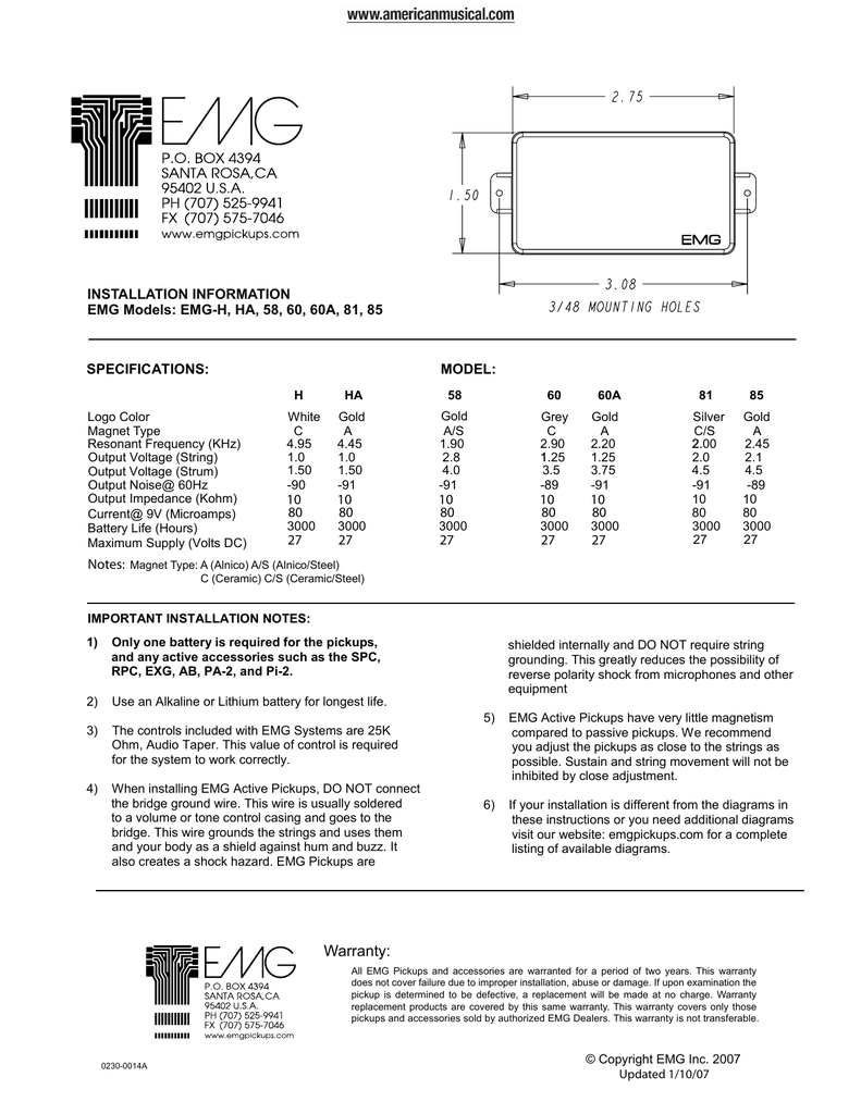
PDF Installation Information Emg Models: Emg-h, Ha, 58, 60 ... Diagram #5 Solder the RED wire from the Battery Holder and/or pickups and re-insert the Header into the insulation cover 1 3 Soldering to the battery buss: If your instrument has an older EMG Pickup you can solder the pickup RED wire to the buss. Simply use some needle nose pliers, pull out the V+ header and solder the RED Wire from the pickup(s)
EMG Pickups / Top EMG Wiring Diagrams / Electric Guitar ...
Emg Wiring Diagram Solderless Listing of EMG Top 10 active pickup wiring diagrams for EMG 81, 85, 89, S, SA, Zakk 2 89s, 2 volume, 1 tone, Solderless · 3 Pickups, SPC/EXG, Hardwired. All of the solderless components for install in one package! This kit is for active pickups and includes everything needed for installation in a 1 or 2 pickup. Top 10 Wiring Diagrams.

EMG 81 85 wiring - Electronics Chat - ProjectGuitar.com
EMG Solderless Wiring - Strange Guitarworks I do a lot of wiring in my shop. I like it - for some reason I find a hot soldering iron soothing. Unfortunately, EMG pickups are attempting to take away my love of soldering with their so-called solderless connections. EMG has been moving towards solderless connections on all their stuff since 2009, and for the most part this works quite well - except when you're integrating an EMG ...

Amazon.com: EMG 3 Pickup Conversion Wiring Kit : Musical ...
Facebook - dmca.com Choose: Choose: Custom Logo Add logos to all protected items: Custom creator profile A public list that shows all the items a creator/owner has in DMCA system: Digital Ink Signature Sign with your mobile, tablet, finger, mouse, touchpad etc. : Add Items Items add to dmca.com content registry. Get your content registered in a globally recognized 3rd party system.

EMG Solderless Wiring - Strange Guitarworks
Emg Solder Wiring Diagram The Wiring | Dubai Khalifa Feb 13, 2022 · For emg pickups, the white wire is the signal output and the metal braid is the ground for the signal and power. original emg wiring diagram solder. if you or anyone has any emg active wiring questions, please feel free to ask me. 21 pictures of emg 81 85 wiring diagram solder.

Emg Wiring Guide | Pick up, Guitar building, The cure
Emg Wiring Diagram - Wirings Diagram As stated earlier, the traces at a Emg Wiring Diagram signifies wires. Sometimes, the cables will cross. However, it doesn't imply link between the wires. Injunction of 2 wires is generally indicated by black dot in the junction of two lines. There will be main lines that are represented by L1, L2, L3, and so on.
Help with EMG wiring (please and thank you) | TalkBass.com
Repository of EMG wiring Diagrams! | Metal Guitarist Forums Repository of EMG wiring Diagrams! Tags diagrams emg ... of the more esoteric configs like using a single push-pull as both master volume and the pickup selector as well as the diagrams for those 3 mini-toggle Charvel/Jacksons like the Model 4, as well as some super-wacky ones like wiring an 89 with a passive pickup with 3 accessory circuits up ...
SA/SA/81
Original EMG Wiring Diagrams - GuitarElectronics.com Listing of EMG Top 10 active pickup wiring diagrams for EMG 81, 85, 89, S, SA, Zakk Wylde, bass pickups and SPC & EXG EQ circuits.
EMG Pickups / Top EMG Wiring Diagrams / Electric Guitar ...
[QUESTION] EMG Pickups To Solder or Not To Solder : Guitar [QUESTION] EMG Pickups To Solder or Not To Solder. Close. 0. Posted by 1 year ago. Archived ... a 3-way switch, and in lieu of the tone knobs putting in a killswitch and an 18v DPDT switch. I have a wiring diagram for this setup, but I think my pickup connector cables are messed up. Every older EMG wiring diagram I could find shows a Red, ...
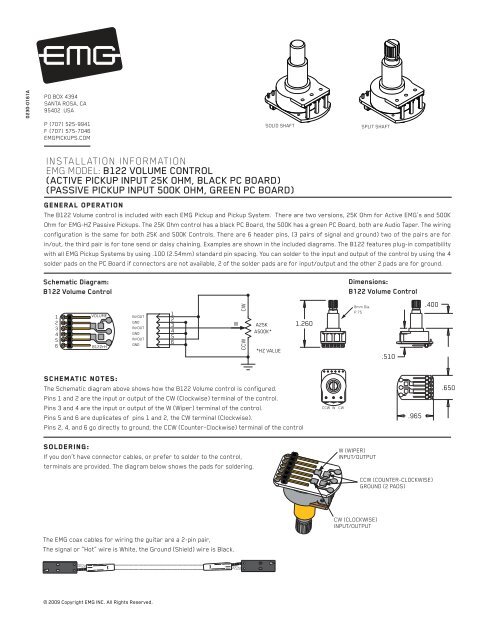
Volume Control Instructions - EMG Pickups
PDF Installation Information Emg Model: Emg-lj Pickup (4/5-string) Diagram #8 1 3 Soldering to the battery buss: If your instrument has an older EMG Pickup you can solder the pickup RED wire to the buss. Simply use some needle nose pliers, pull out the V+ header and solder the RED Wire from the pickup(s) to any of the pins and then re-insert the header into the housing. 2 +18 Volt Wiring Option:

Emg solderless setup issues with the toggle switch. : r/diyguitar
Question about soldering EMG pickups | SevenString.org Berkeley, CA. Apr 26, 2007. #1. I've had my EMG Zakk Wylde set (81/85) for about 5 months now and I'm STILL not done installing them. Basically Ibanez does not like routing the pickup cavities deep enough, my 3 way pickup switch that I got for $4 on eBay was complete shit, and my volume control is fucked up, so while it makes sound, I can't use ...
EMG JV-X Set Wiring Diagram
Humbucker Series/Parallel - GuitarElectronics.com This guitar wiring modification shows how to use a two position double pole-double throw On/On mini switch or a standard push/pull pot to select series or parallel modes. In humbucker mode, the output will be strong with a smooth attack and a deep tone. In parallel mode, the sound will be very clean and sparkly with lower output. Note: Both ...
EMG DG20 (David Gilmour set) Wiring Question | Fender ...
PDF Installation Information Emg Models: T & Tc Sets EMG Models: T & TC SET OUTPUT JACK T R S BOTTOM VIEW Mounting the Controls: Refer to Diagram #5 1) Remove the existing controls from the control plate and mount the EMG controls as shown to the right. Be sure the PC Board on the switch is facing the same direction as the diagram shows. Diagram #5 Plug in the Pickups: Refer to Diagram #6

One Humbucker – One Volume + Tone – Wiring diagram for EMG HZ ...
PDF Emg Mmcs Wiring Diagram - Preamps | Bartolini | Aguilar Diagram #8 1 3 Soldering to the battery buss: If your instrument has an older EMG Pickup you can solder the pickup RED wire to the buss. Simply use some needle nose pliers, pull out the V+ header and solder the RED Wire from the pickup(s) to any of the pins and then re-insert the header into the housing. 2 +18 Volt Wiring Option:
EMG 40HZ split coil wiring | TalkBass.com

EMG's wiring with 5 way lever - Ultimate Guitar

Custom Guitar Wiring Diagram TWO PICKUPS
![QUESTION] Swapping EMG 81/89tw out of a Schecter Hellraiser C ...](https://external-preview.redd.it/2cPCBa80YHF5pAlrTrVSlHbffwGEYGvT4FPye8Gn86I.jpg?auto=webp&s=7acf4c2f68c11c13426b1e1bb5da688e9674442d)
QUESTION] Swapping EMG 81/89tw out of a Schecter Hellraiser C ...

7 Pickup Installation and Wiring Documentation Resources ...
EMG 81/85 wiring, bad noise | Ibanez JEM Forum
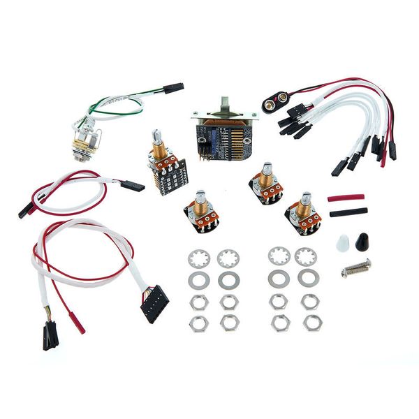
EMG 3 Pickups Push/Pull Wiring Kit
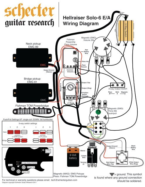
HELLRAISER SOLO 6 WIRING DIAGRAM - Schecter Guitars
Need help with EMG solderless wiring | SevenString.org
EMG Pickups / Top EMG Wiring Diagrams / Electric Guitar ...

Unique Emg Hz Wiring Diagram | 3 way switch wiring, Guitar ...
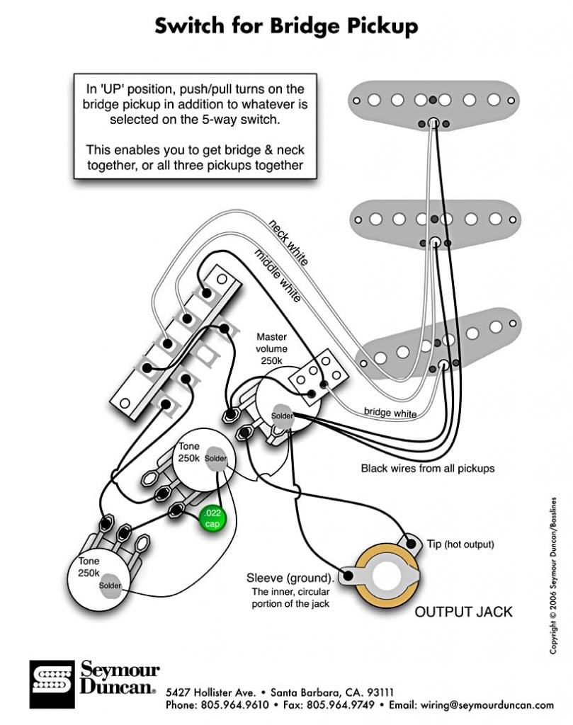
Seymour Duncan Adding A Bridge Pickup Switch To A Strat ...
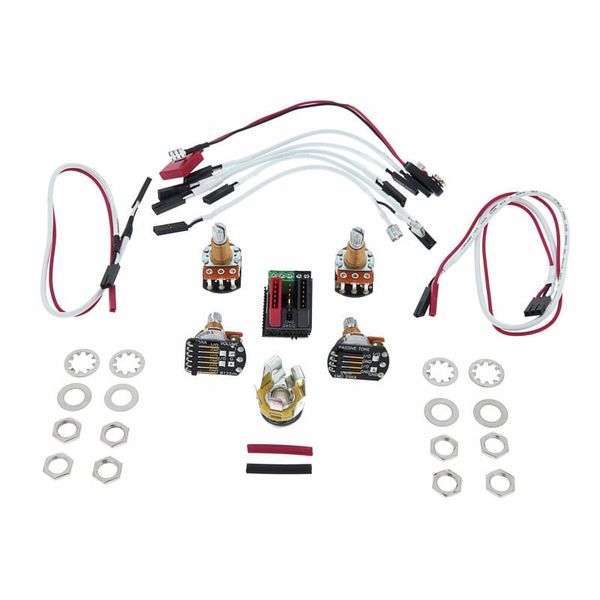
EMG 1 or 2 Pickups Wiring Kit
EMG Pickups / Top EMG Wiring Diagrams / Electric Guitar ...

EMG 1-2 Pickup Conversion Wiring Kit Solderless Long Shaft (Les Paul) 19mm

Les Paul EMG 'Jimmy Page' wiring - Ultimate Guitar

EMG 245D For 2 Pickups In / Out Battery Buss & Switch Connection For Active Or Passive 5052.00
Who's got an OLD STYLE EMG SSS wiring schematic ? - Music ...
My EMG 81/85 setup Pic. Need advice - Ultimate Guitar
EMG Active Humbucker Installation Manual | Manualzz
EMG problem.. - Ultimate Guitar
Needing Wiring Diagram | My Les Paul Forum

EMG Solderless Wiring Kit for 1-2 Active Pickups - Short Shaft (Strat) 10mm

SOLVED: I have a Jackson Kelly and I just got new EMG - Fixya
EMG wiring question: 81/85, 1 vol, no tone. | Rig-Talk
EMG Pickups / Top EMG Wiring Diagrams / Electric Guitar ...
EMG MMCS pickup wiring. | TalkBass.com

Strat Style Guitar Wiring Diagram
0 Response to "43 emg wiring diagram solder"
Post a Comment