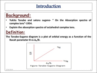
41 d3 tanabe sugano diagram
D3 Tanabe Sugano Diagram - schematron.org Using a Tanabe-Sugano diagram for a d3 system this ratio is found at Δ/B= Tanabe-Sugano diagram for d3 octahedral complexes Interpolation of the graph to find the Y-axis values for the spin-allowed transitions gives. d2 Tanabe-Sugano diagram. d3 Tanabe-Sugano diagram. d4 Tanabe-Sugano diagram. d5 Tanabe-Sugano diagram. PDF Advanced Inorganic Chemistry - UM Tanabe-Sugano diagrams, the energy axis has units of E/B. The xaxis has - units of "o /B. Each TanabeSugano diagram is given for only one specific - B/C ratio (the best value). For example, the TanabeSugano diagram for d- 3 complexes is given for C=4.5 B. non-crossing rule: Terms of the same symmetry cannot cross and will 'repel' each ...
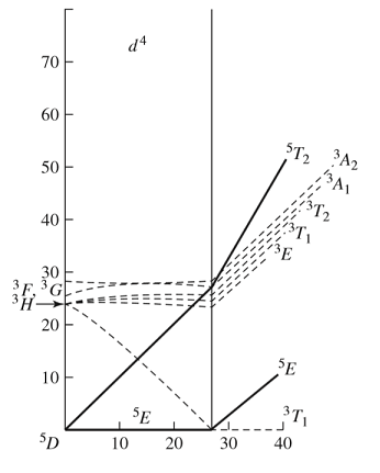
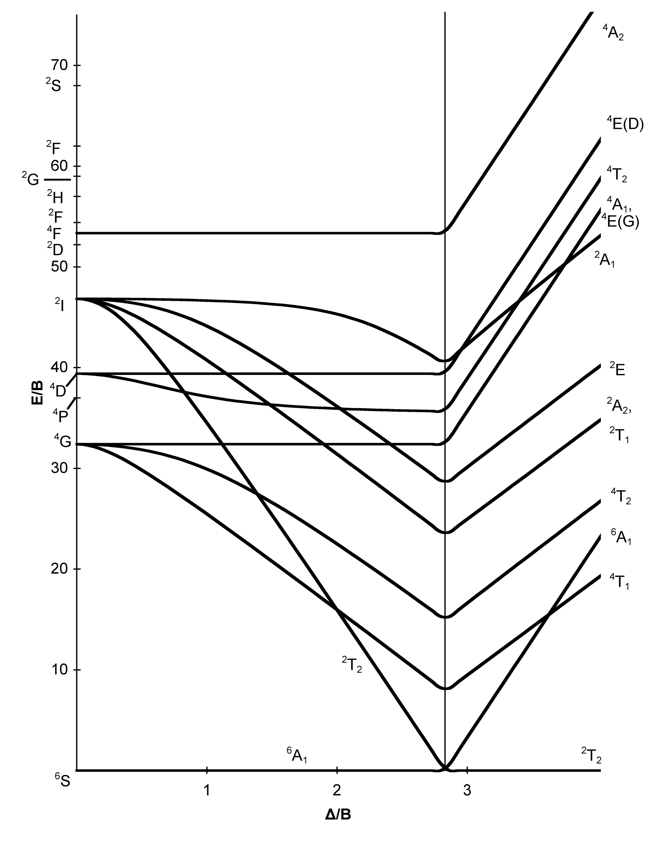
Tanabe-Sugano diagram - Self-sufficiency Certain Tanabe-Sugano diagrams (d 4, d 5, d 6, and d 7) also have a vertical line drawn at a specific Dq/B value, which corresponds with a discontinuity in the slopes of the excited states' energy levels.This pucker in the lines occurs when the spin pairing energy, P, is equal to the ligand field splitting energy, Dq.
D3 tanabe sugano diagram
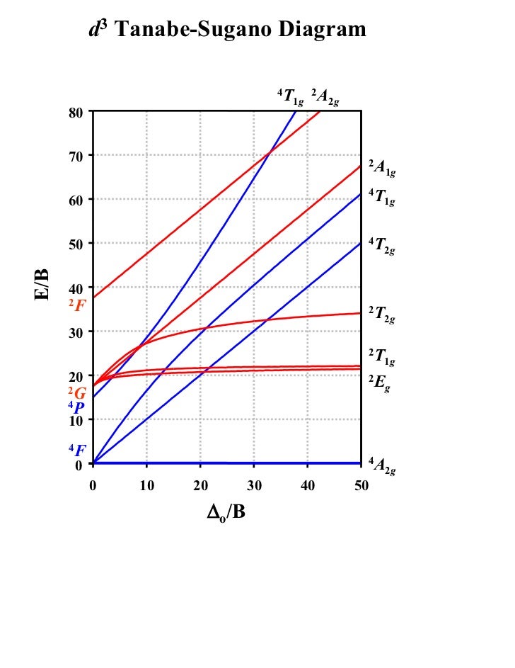
File:D3 Tanabe-Sugano Calcdiagram.svg - Wikimedia Commons English: d3 Tanabe Sugano diagram in colour and with allowed and forbidden lines calculated by CAMMAG with B=933 and C=4199 cm-1 and imported into Excel and then converted to SVG Date 27 March 2019 PDF Coordination Chemistry III: Tanabe-Sugano Diagrams and ... d7Tanabe-Sugano Diagram E / B ∆o/ B 4F 2G 2Eg 2T1g 2A1g 2T2g 4P 4A 2g 4T 1g ( 4P) 4T 2g 4T 1g ( 4F) Complexes with d4-d7 electron counts are special •at small values of ∆o/B the diagram looks similar to the d2diagram •at larger values of ∆o/B, there is a break in the diagram leading to a d3 Tanabe-Sugano diagram d3 Tanabe-Sugano diagram. A Tanabe-Sugano diagram of the spin-allowed and low-lying spin-forbidden transitions for octahedral d 3 and tetrahedral d 7 complexes is given below. Select the region of interest then click on the curve to get your parameters. See the instructions for more information. For the d 3 case, the ground term is 4 A 2g which ...
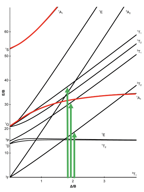
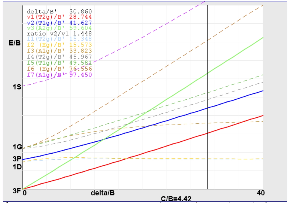
D3 tanabe sugano diagram. Calculations using Tanabe-Sugano diagrams Using a Tanabe-Sugano diagram for a d3 system this ratio is found at Δ/B=24.00. Tanabe-Sugano diagram for d3 octahedral complexes. Interpolation of the graph to find the Y-axis values for the spin-allowed transitions gives: ν1/B=24.00 ν2/B=33.90 ν3/B=53.11 Recall that ν1=17000 cm-1. Therefore for the first spin-allowed transition, File:Tanabe Sugano Diagram d3.svg - Wikimedia Commons d3 Tanabe-Sugano Diagram. Summary . Description: English: The Tanabe-Sugano diagram for a d 3 transition metal ion. The energies are calculated using a Racah C = 4.5 B, and only selected states are depicted. Transitions from the quartet ground state to doublet excited states (dotted) are spin-forbidden. Solved The Cr3+ complex [Cr(H2O).]3+ exhibits UV/vis/NIR ... Use the d3 Tanabe-Sugano diagram to determine (estimate) the correct; Question: The Cr3+ complex [Cr(H2O).]3+ exhibits UV/vis/NIR absorption features at 581 nm and 400 nm. First, convert the absorption features from units of 'nm'to'cm-1, rounding to the nearest 100. Then, using the method of analysis discussed in class, calculate B and 10Dq (in ... PDF Tanabe -Sugano Diagram - Mercyhurst University d3 Tanabe-Sugano Diagram d2 Tanabe-Sugano Diagram . d5 Tanabe-Sugano Diagram d4 Tanabe-Sugano Diagram . d6 Tanabe-Sugano Diagram . d8 Tanabe-Sugano Diagram . Author: Jircitano, Kellie Created Date: 3/14/2011 4:00:24 PM ...
PDF Orgel and Tanabe-Sugano Diagrams for Transition Metal ... Orgel and Tanabe-Sugano Diagrams for Transition Metal Complexes (d1 - d9 States) It is a well-known fact that electronic transitions are always accompanied by vibrational as well as rotational changes which results in a considerable broadening of the bands in the UV-visible spectra of transition metal complexes too. PDF d 2 Correlation Diagram - University of Massachusetts Boston Notes on d7 Tanabe-Sugano Diagram!The d 7 diagram, like all such diagrams for configurations that may be either high spin or low spin, has a perpendicular line near the middle marking the change in spin state. "To the left of the line (low field strength, high spin), the ground state is 4T 1, emerging from the free-ion 4F term. Tanabe Sugano Diagram of d3 complex - YouTube Spectroscopic Term Symbol File:Tanabe Sugano Diagram d3.svg - Wikipedia English: The Tanabe–Sugano diagram for a d3 transition metal ion. The energies are calculated using a Racah C = 4.5 B, and only selected states are depicted ...
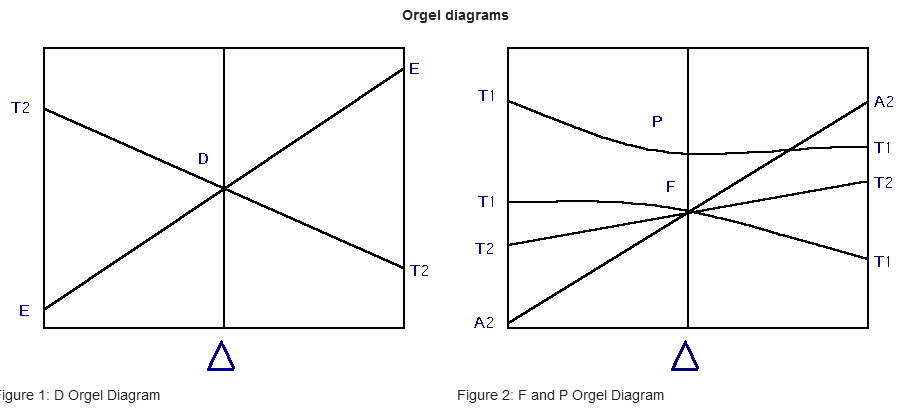
PDF 13 Tanabe Sugano Diagrams - MIT Lecture 4 May 11: Tanabe Sugano Diagrams A Tanabe-Sugano (TS) diagram plots the energy dependence of the various ligand field states (or terms) with field strength. The strength of the ligand field is defined by Dq, which is related to the octahedral crystal field splitting by 10Dq = ∆o. The energy of the state is given by E. What is B in Tanabe Sugano diagram? - Runyoncanyon ... For the F Orgel diagram, the left side contains d2 and d7 tetrahedral and d3 and d8 octahedral complexes. ... Tanabe-Sugano diagrams can also be used to predict the size of the ligand field necessary to cause high-spin to low-spin transitions. In a Tanabe-Sugano diagram, the ground state is used as a constant reference. ... Tanabe Sugano Diagram - d7 system - YouTube A step-by-step tutorial on assigning the transitions in the UV-vis spectrum of a d7 system using a Tanabe-Sugano Diagram. Tanabe-Sugano Diagram for D3 Electron Configuration in ... Racah Parameters. Racah parameters were generated as a means to describe the effects of electron-electron repulsion within the metal complexes. The Racah parameters are A, B and C.In the case of Tanabe-Sugano diagrams each electron configuration split has an energy that can be related by the B value.
Electronic Spectroscopy.key
PDF Coordination Chemistry III: Tanabe-Sugano Diagrams d2Tanabe-Sugano Diagram E / B ∆o/ B 3F 3P 3T 1g (3P) 3A 1g 3T 2g (3F) 3T 1g ~15B ~∆o ~∆o E1 E2 E3 E is the energy of the excited state relative to the ground state B is the Racah parameter for e--e-repulsion The example on page 427 of your text shows how to use this chart to fit the experimental data (E1, E2, and E3) for [V(OH2)6]3+to ...
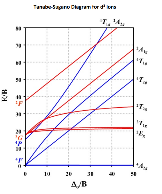
Solved Tanabe-Sugano Diagram for d3 ions *T1, 242g 80 70 ...
PDF Calculation of Dq, B and β Parameters - Dalal Institute The Orgel and Tanabe-Sugano diagram for d2-configuration can be used to estimate the value of crystal field splitting energy for these transition metal complexes. (a) (b) Figure 38. The (a) Orgel and (b) Tanabe-Sugano diagrams for d2 complexes in the octahedral crystal field. Consider the example of [V(H2O)6]3+. 1.
Interpretation of the Emission Spectra of Trivalent Chromium ...
Tanabe-Sugano Diagrams - Chemistry LibreTexts 15 Aug 2020 — Tanabe Sugano diagrams are used to predict the transition energies for both spin-allowed and spin-forbidden transitions, as well as for both ...

Tanabe-Sugano diagram for a 3d 2-ion in an ideal tetrahedral ...
Diagram Tanabe Sugano | Inorganic Chemistry | Mechanics Cr has 6 electrons. Cr3+ has three electrons so its has a d-configuration of d3 2. Locate the d3 Tanabe-Sugano diagram. 3. Convert to wavenumbers: 4. Allowed transitions are. 5. Sliding the ruler perpendicular to the x-axis of the d 3 diagram yields the following values: 6. Based on the two tables above it should be assessed that the oct/B ...
Explain the difference between Orgel and Tanabe-Sugano ...
Tanabe-Sugano Diagram - Parameters Certain Tanabe-Sugano diagrams (d4, d5, d6, and d7) also have a vertical line drawn at a specific Dq/B value, which corresponds with a discontinuity in the slopes of the excited states' energy levels. This pucker in the lines occurs when the spin pairing energy, P, is equal to the ligand field splitting energy, Dq.

Datei:D4 Tanabe-Sugano diagram.png – Wikipedia
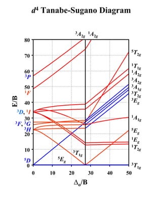
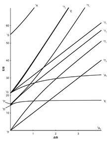
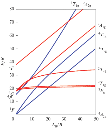
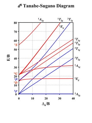
(PDF) Tanabe-Sugano Diagram | Sari Syahruni - Academia.edu d2 Tanabe-Sugano Diagram 1A 1E 1g g 80 3A 2g 70 60 1T 1g 1T 1S 2g 3T 50 1g E/B 40 3T 2g 1A 1g 30 1G 20 1E 3P g 1D 1T 2g 10 3F 3T 0 1g ∆o/B 0 10 20 30 40 d3 Tanabe-Sugano Diagram 4T 2 1g A2g 80 70 2A 1g 4T 60 1g 50 4T 2g E/B 40 2F 2T 2g 30 2T 1g 20 2E 2G g 4P 10 4F 4A 0 2g ∆o/B 0 10 20 30 40 50 d4 Tanabe-Sugano Diagram 3A 1 2g A2

Electronic Spectra of Coordination Compounds - ppt download
D8 Tanabe Sugano Diagram Tanabe-Sugano diagrams are used in coordination chemistry to predict electromagnetic absorptions of metal coordination compounds of. d3 Tanabe-Sugano Diagram. 0. 0. 10 . d8 ν. 2. /ν. 1. Ratio. 0. 5. 10 15 20 25 30 35 ∆ o.

Tanabe-Sugano diagram for the d 3 electron configuration in ...
D7 Tanabe Sugano Diagram - schematron.org The baseline in the Tanabe-Sugano diagram represents the lowest energy or ground term state. The d 2 case (not many examples documented). The electronic spectrum of the V 3+ ion, where V(III) is doped into alumina (Al 2 O 3), shows three major peaks with frequencies of: ν1= cm-1, ν2= cm-1 and ν3= cmFile:D7 Tanabe-Sugano schematron.org ...
![Why does [Cr(NH3)6]3+ have two absorptions for the eg*t2g ...](https://slideplayer.com/slide/10328870/35/images/16/Tanabe-Sugano+diagram+for+d2.jpg)
Why does [Cr(NH3)6]3+ have two absorptions for the eg*t2g ...
PDF d Tanabe-Sugano Diagram Title: Microsoft PowerPoint - handout6b Author: Alan Jircitano Created Date: 11/22/2004 11:06:49 PM
File:D5 Tanabe-Sugano diagram.png - Wikimedia Commons
Solved 2. Tanabe-Sugano diagrams The octahedral ... Tanabe-Sugano diagrams The octahedral coordination complex [Cr(brap)6]3+ has a ΔO value of 18,000 cm-1 and a B of 600 cm-1. The d3 Tanabe Sugano diagram is shown below. a) Determine the energy of all allowed transitions and the lowest energy forbidden transition in cm-1. Show your work.
Tanabe sugano diagram
D3 Tanabe Sugano Diagram - wiringall.com Tanabe-Sugano diagrams are used in coordination chemistry to predict electromagnetic absorptions of metal coordination compounds of. Tanabe-Sugano diagram for d3 octahedral complexes. TS d3 diagram. Interpolation of the graph to find the Y-axis values for the spin-allowed transitions gives. The different free ion terms for an electron ...

Tanabe-Sugano diagram for d 3 | Download Scientific Diagram
Tanabe–Sugano diagram - Wikipedia Certain Tanabe-Sugano diagrams (d 4, d 5, d 6, and d 7) also have a vertical line drawn at a specific Dq/B value, which is accompanied by a discontinuity in the slopes of the excited states' energy levels.This pucker in the lines occurs when the identity of the ground state changes, shown in the diagram below. The left depicts the relative energies of the d 7 ion states as functions of ...

Tanabe Sugano Diagram with Examples, Spin Crossover, Questions from CSIR NET and GATE
T sdiagram - slideshare.net T sdiagram. 1. d2 Tanabe-Sugano Diagram 1A 1E 1g g 80 3A 2g 70 60 1T 1g 1T 1S 2g 3T 50 1g E/B 40 3T 2g 1A 1g 30 1G 20 1E 3P g 1D 1T 2g 10 3F 3T 0 1g 0 10 20 30 40 ∆o/B. 2. d3 Tanabe-Sugano Diagram 4T 1g A2g 2 80 70 2A 1g 4T 60 1g 50 4T 2g E/B 40 2F 2T 2g 30 2T 1g 20 2E 2G g 4P 10 4F 4A 0 2g 0 10 20 30 40 50 ∆o/B.

Figure 2.4 from Synthetic approaches to cis,cis-1,3,5 ...
d3 Tanabe-Sugano diagram d3 Tanabe-Sugano diagram. A Tanabe-Sugano diagram of the spin-allowed and low-lying spin-forbidden transitions for octahedral d 3 and tetrahedral d 7 complexes is given below. Select the region of interest then click on the curve to get your parameters. See the instructions for more information. For the d 3 case, the ground term is 4 A 2g which ...
Chromium complexes for luminescence, solar cells, photoredox ...
PDF Coordination Chemistry III: Tanabe-Sugano Diagrams and ... d7Tanabe-Sugano Diagram E / B ∆o/ B 4F 2G 2Eg 2T1g 2A1g 2T2g 4P 4A 2g 4T 1g ( 4P) 4T 2g 4T 1g ( 4F) Complexes with d4-d7 electron counts are special •at small values of ∆o/B the diagram looks similar to the d2diagram •at larger values of ∆o/B, there is a break in the diagram leading to a
GitHub - sewahl/Python3-for-Tanabe-Sugano: This is a Python3 ...
File:D3 Tanabe-Sugano Calcdiagram.svg - Wikimedia Commons English: d3 Tanabe Sugano diagram in colour and with allowed and forbidden lines calculated by CAMMAG with B=933 and C=4199 cm-1 and imported into Excel and then converted to SVG Date 27 March 2019
8.2: Term splitting in ligand fields, selection rules, Tanabe ...

Tanabe Sugano Diagram - d7 system
BSc Chemistry
T sdiagram
T sdiagram
M.Sc Chemistry Inorganic Chemistry Semester-II
Tanabe-Sugano-Diagramm – Wikipedia
Optical Spectroscopy of Disordered Langasites Doped with ...
Interpretation of the spectra of first-row transition metal ...
Explain the difference between Orgel and Tanabe-Sugano ...
Orgel and Tanabe-Sugano Diagrams for Transition Metal ...

Orgel and Tanabe-Sugano Diagrams for Transition Metal ...
Coordination Chemistry III: Tanabe-Sugano Diagrams and Charge ...
T sdiagram

Analyzing an Octahedral Co(III) Complex Using a d6 Tanabe-Sugano Diagram
Tanabe-Sugano Diagram for d3 ions807060503 40 2F3020 ...
Electronic Spectroscopy

Tanabe-Sugano diagram for the d 8 electron configuration in ...
Tanabe–Sugano diagram - Wikipedia

Electronic Spectra of Transition Metal Complexes --- Part 5: Tanabe-Sugano Diagrams for d2 and d7
Electronic Selection Rules (II)

T sdiagram

File:Tanabe Sugano Diagram d5.svg - Wikimedia Commons
Interpretation of the spectra of first-row transition metal ...
Tanabe–Sugano diagram - Wikipedia
0 Response to "41 d3 tanabe sugano diagram"
Post a Comment