42 draw the moment diagram for the beam. follow the sign convention.
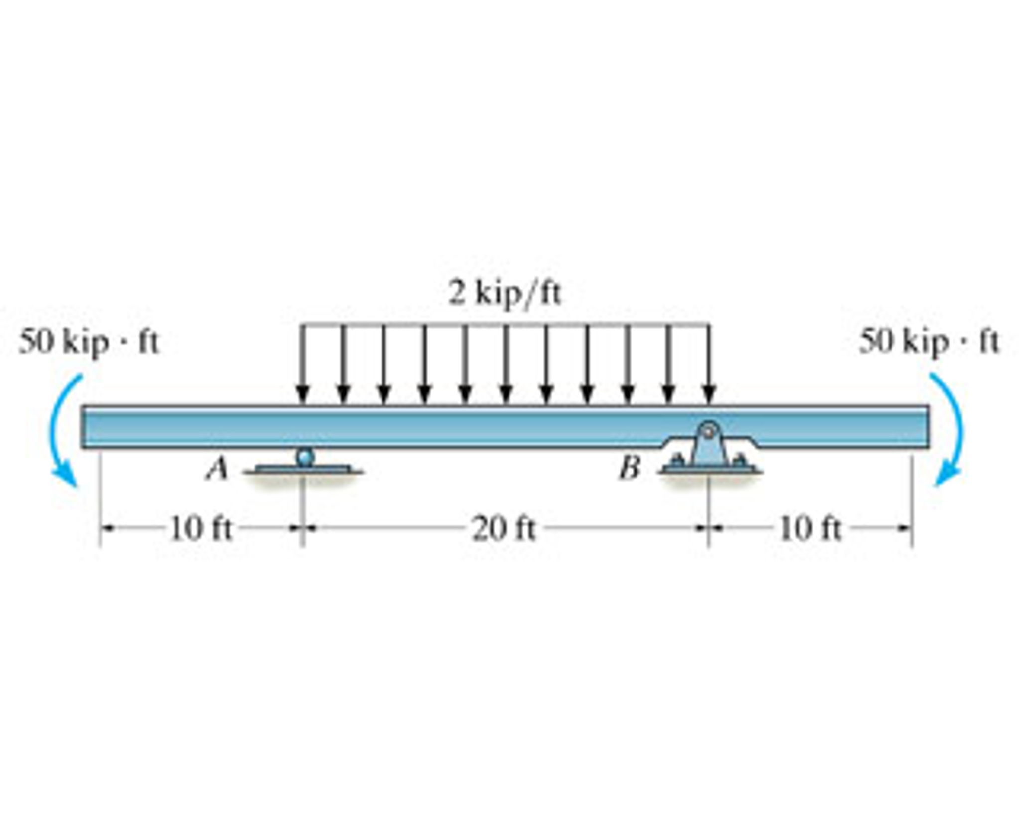
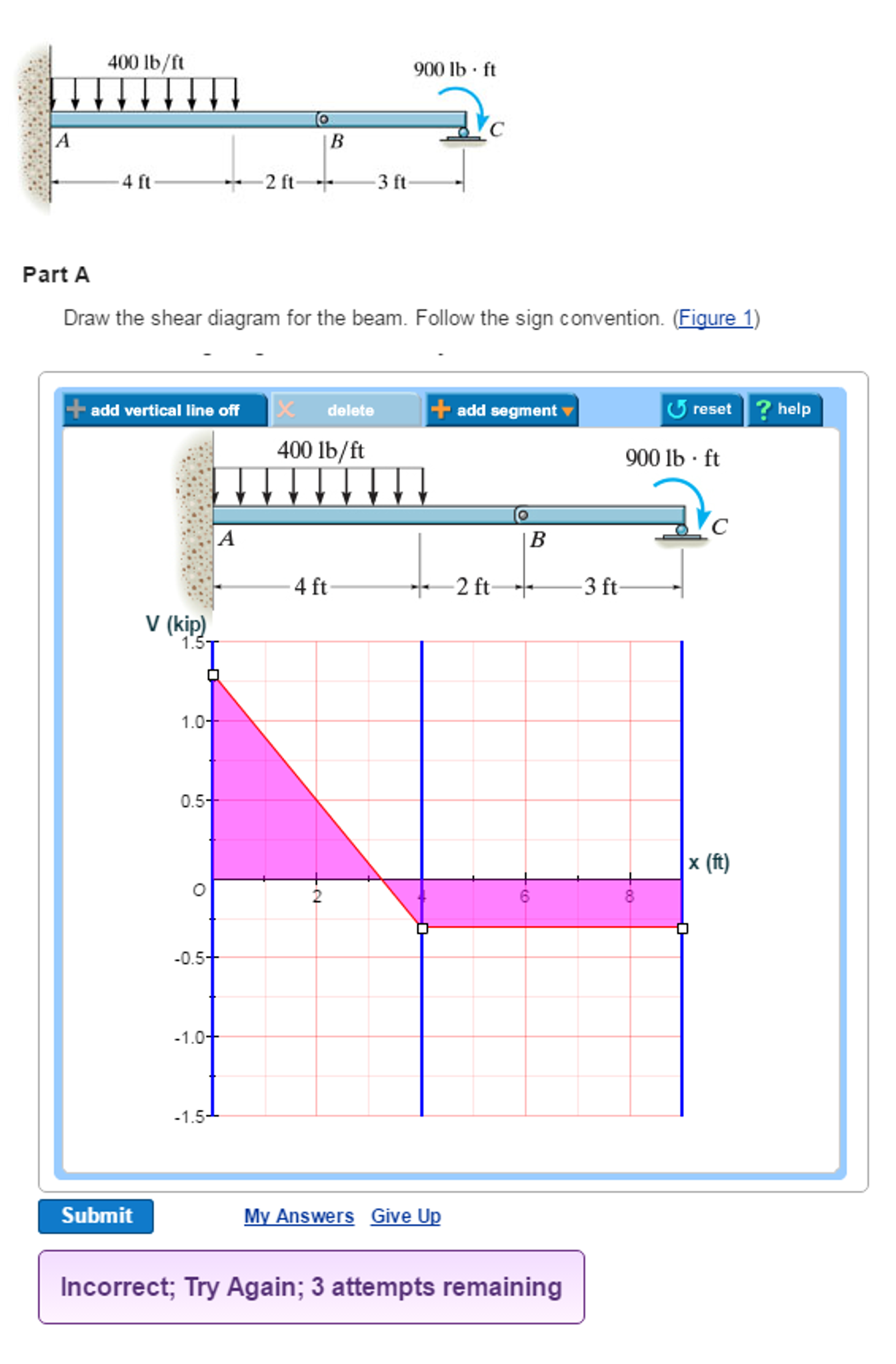
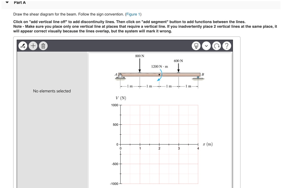
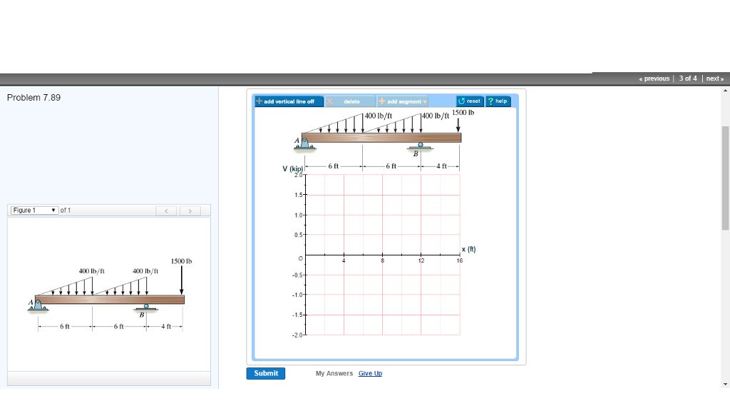
Equations of Equilibrium: Referring to the free-body diagram of the beam shown in Fig. a, a Shear and Moment Diagram: As shown in Figs. b and c. A y = 1000 lb +c©F y = 0; A y + 1000 - 400 - 200(6) - 400 = 0 B y = 1000 lb +©M B y(6) + 400(3) - 200(6)(3) - 400(9) = 0 A = 0; 6-39. Draw the shear and moment diagrams for the double overhanging ... Part A Draw the shear diagram for the beam. Follow the sign convention. (Figure 1) Click on "add vertical line off" to add discontinuity lines. Then click on "add segment" button to add functions between the lines. Note - Make sure you place only one vertical line at places that require a vertical line.
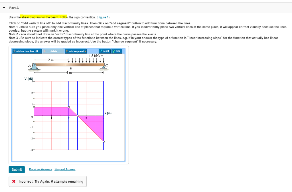
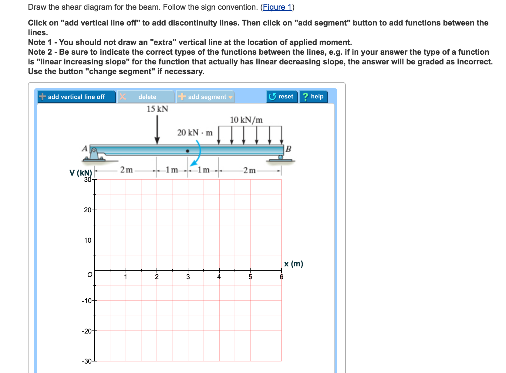
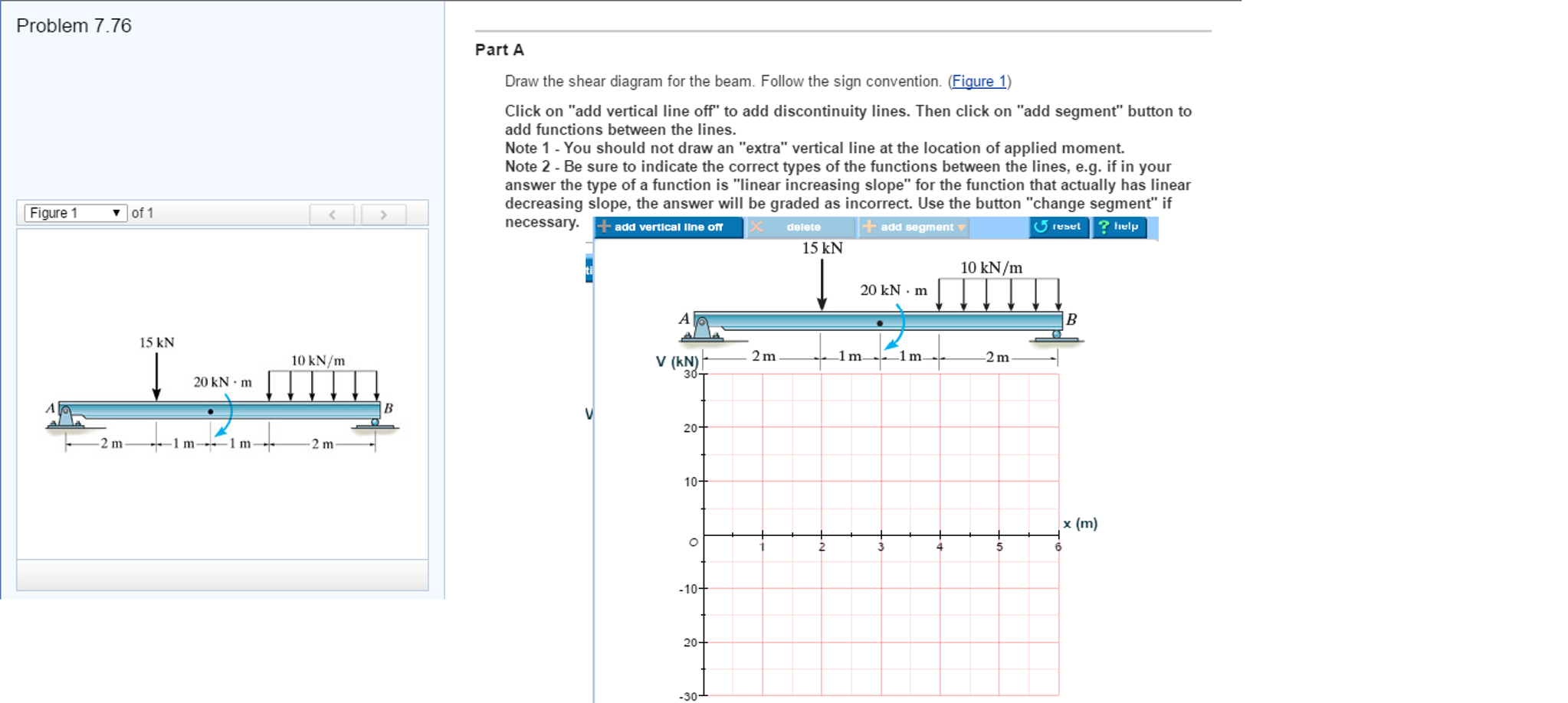
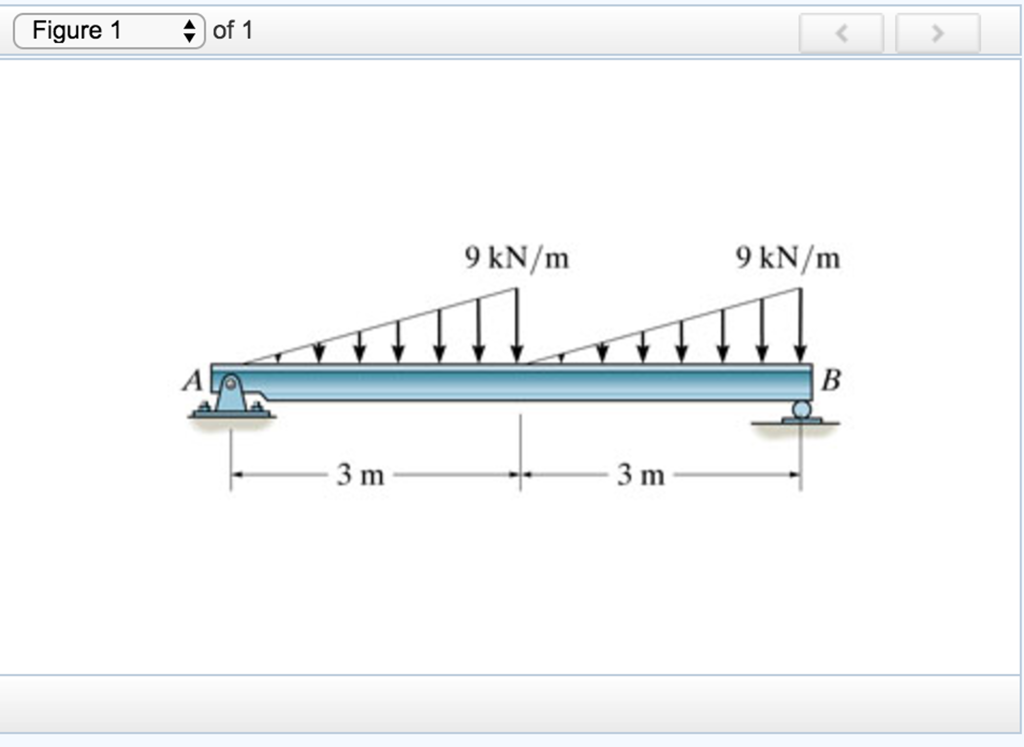
Question: Problem 7.76 Part A Draw the shear diagram for the beam. Follow the sign convention. (Figure 1) Click on "add vertical line off" to add discontinuity lines. Then click on "add segment" button to add functions between the lines. Note 1 Note 2 - Be sure to indicate the correct types of the functions between the lines, e.g. as incorrect.
Draw the moment diagram for the beam. follow the sign convention.
beam from the left hand end and summing up the areas of shear force diagrams using proper sign convention. xThe process of obtaining the moment diagram from the shear force diagram by summation is exactly the same as that for drawing shear force diagram from load diagram. Draw the moment diagram for the beam. Follow the sign convention. Click on "add vertical line off" to add discontinuity lines. Then click on "add segment" button to add functions between the lines. Note 1- Make sure you place only one vertical line at places that require a vertical line. Answer: As long as you are consistent it does not really matter which you consider positive and which you consider negative. To fall in line with general practice I recommend you consider sagging moment as positive and hogging moment as negative. Draw the BM diagram consistently on the tension ...
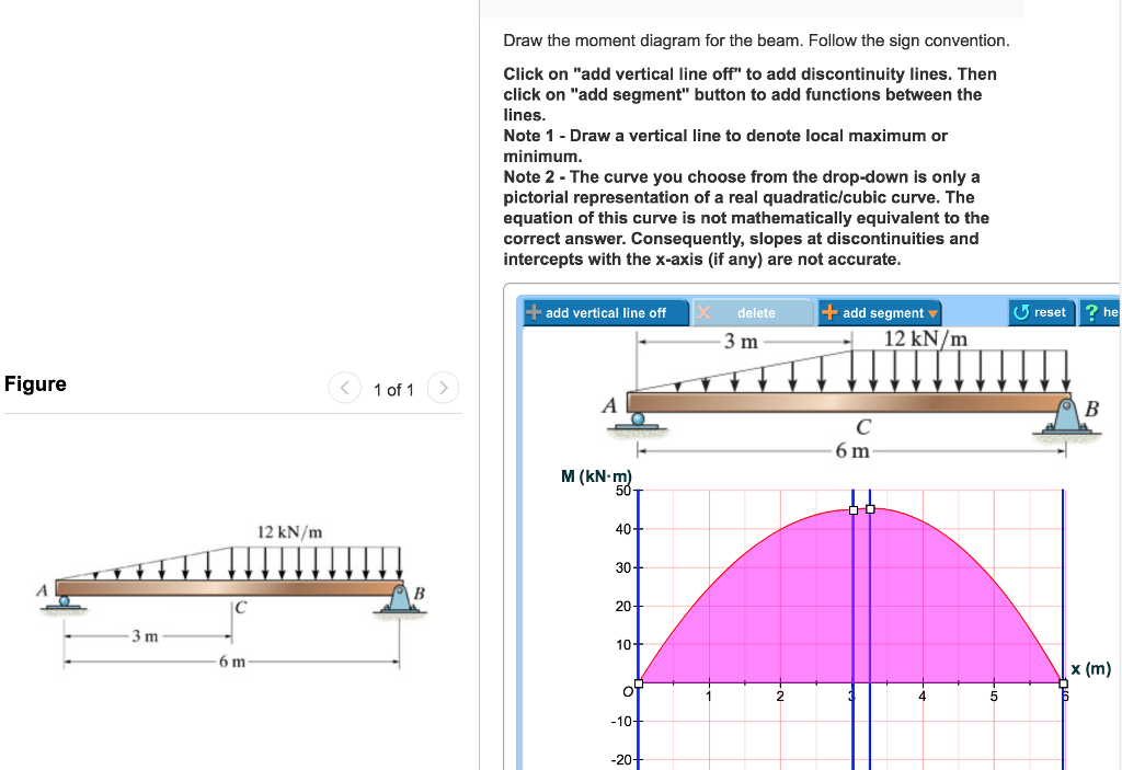
Draw the moment diagram for the beam. follow the sign convention.. See the answer See the answer done loading. Problem 7.87. Part A. Draw the shear diagram for the beam. Follow the sign convention. Part B. Draw the moment diagram for the beam. Follow the sign convention. Show transcribed image text. and the bending moment diagrams follow from these equations. 1. The load intensity w at any section of a beam is equal to the negative of the slope of the shear force diagram at the section. Proof-follows directly from Eq. (4.1). 2. The shear force V at any section is equal to the slope of the bending moment diagram at that section. Draw the moment diagram for the beam. Follow the sign convention. Click on "add vertical line off" to add discontinuity lines. Then click on "add segment" button to add functions between the lines. Note 1 - Draw a vertical line to denote local maximum or minimum. 1.3.2017 · Another approach is to take a fixed sign convention where we ignore any preconceived ideas about loading direction. This is useful when we are unsure of the loading or reaction sense. It avoids a situation where we’ve assumed a compressive reaction that turns out to be tensile load and we can end up with a double negative in the diagram!
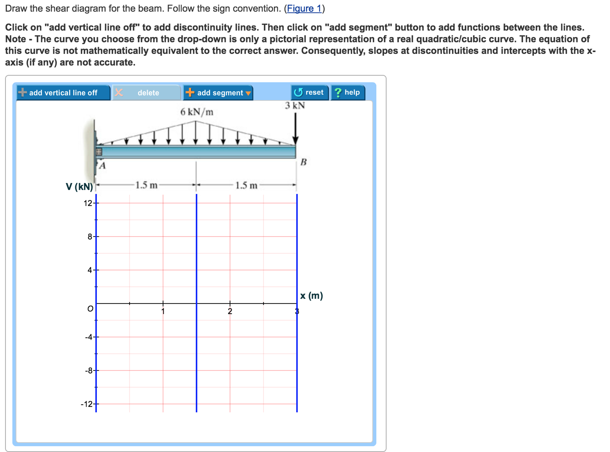
as the real beam is fixed supported. Due to displacement of the real beam at B, the moment at the end B` of the conjugate beam must have a magnitude of .Summing moments about B` we have, - By our sign convention the induced moment is negative, since for equilibrium it acts counter clockwise on the member. The three most prominent internal forces in structural analysis calculations are the bending moment, shear force, and axial force. It is very common for people to define and state their sign convention before proceeding with any structural analysis problem. This is mainly due to variations in the selection of positive and negative coordinates. Problem 7.80 3 of 3 Draw the shear diagram for the beam. Follow the sign convention. (Figure 1) Click on "add vertical line off" to add discontinuity lines. Then click on "add segment" button to add functions between the lines. Note 1 You should not draw an "extra" discontinuity line at the point where the curve passes the x-axis. When the shear diagram is decreasing, the moment diagram is concave downward. Sign Convention The customary sign conventions for shearing force and bending moment are represented by the figures below. A force that tends to bend the beam downward is said to produce a positive bending moment.
shear force and bending moment and also some basic concepts of strength of materials in our recent posts. We have already seen the various types of beams and different types of loads on beam during our previous posts. Today we will see here the sign conventions for shear force and bending moment diagram in subject of strength of materials with the help of this post. Question: Draw the shear and moment diagram for the beam.Problem 7-71 from:Engineering Mechanics: Statics, 14th editionRussell C. HibbelerThank you guys for ... 31.12.2016 · Example On Cantilever Beam Problem :- Calculate the value and draw a bending moment and shear force diagram for following cantilever beam shown in fig. 31/12/16 RAVI VISHWAKARMA 15 16. Solution Problem The support reaction for given beam can be easily determined by following method. Dy = (4×2 ×1/2) + (2 ×4) Dy =10 kN 31/12/16 RAVI … Bending Moment Diagrams are used to represent the bending moment forces that act along the length of a beam. Most of the time, the beam undergoes forces in the negative Y direction due to gravity. This generally induces a positive bending moment as the beam will sag or drop. The first case: a positive bending moment shows as negative on the ...
Solved: Draw The Shear Diagram For The Beam. Follow The Si ...
Shear Stress Questions and Answers. Get help with your Shear stress homework. Access the answers to hundreds of Shear stress questions that are explained in a …
Solved: Draw The Moment Diagram For The Beam. Follow The S ...
Consider the beam shown in (Figure 1) . Follow the sign convention. Draw the shear diagram for the beam. Draw the moment diagram for the beam. Fundamental Problem 4.13 Considor tho beam shown in Eguro 10. Follow tho sign convention. 2 m 2 m Part A...
Solved: Draw The Moment Diagram For The Beam. Follow The S ...
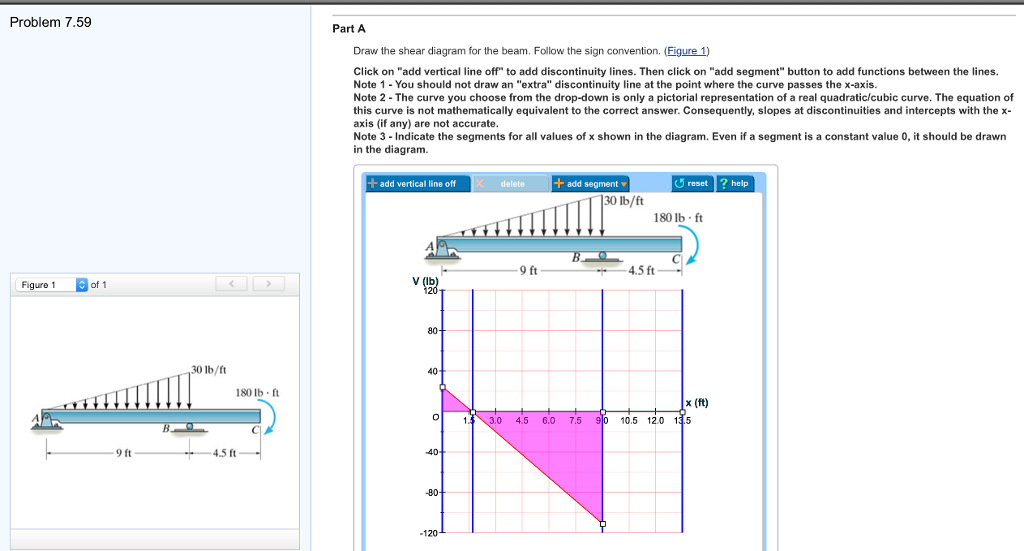
Problem 7.59 Part A Draw the shear diagram for the beam. Follow the sign convention. (Figure 1) Click on "add vertical line off" to add discontinuity lines. Then click on "add segment" button to add functions between the lines. Note 1- You should not draw an "extra" discontinuity line at the point where the curve passes the x-axis Note 2 The ...
Solved: Draw The Shear Diagram For The Beam. Follow The Si ...
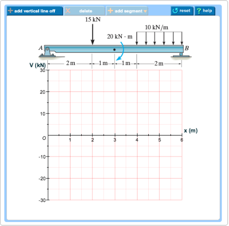
Draw the moment diagram for the beam. Follow the sign convention. (Figure 1)Click on "add vertical line off" to add discontinuity lines. Then click on "add segment" button to add functions between the lines. Note 1 - You should not draw an "extra" discontinuity line at the point where the curve passes the x-axis.

I AM BOLD
Problem 7.59 Part A Draw the shear diagram for the beam. Follow the sign convention. (Figure 1) Click on 'add vertical line off to add discontinuity lines. Then click on "add segment" button to add functions between the lines. Note 1 - You should not draw an "extra" discontinuity line at the point where the curve passes the x-axis.

Draw The Shear Diagram For The Beam Follow The Sign ...
RE: Moment Diagram Sign Convention Poll. paddingtongreen (Structural) 11 Feb 11 19:47. putting the BM above the beam was fine, it was positive, below the line was negative. Then I moved on to fixed ended beams and the direction of rotation got a sign, clockwise positive and anti clockwise negative, or vice versa.
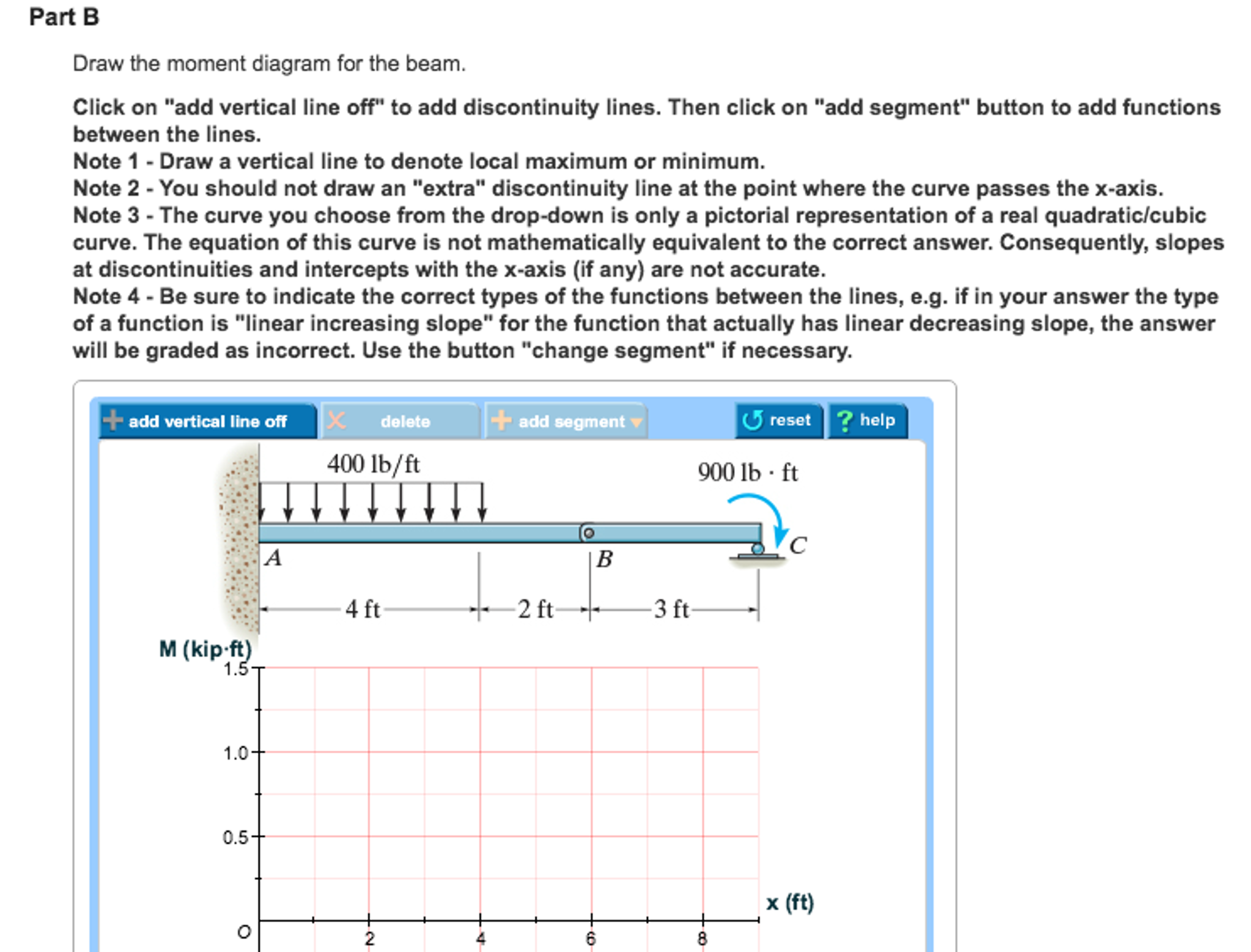
Solved: Part B Draw The Moment Diagram For The Beam. Follo ...
The and plots are referred to as shear force diagram (SFD) and bending moment diagram (BMD) respectively. Example 7.2.1. Determine the and for the loaded beam shown in the figure. SOLUTION. 1- Draw the FBD of the beam. In the FBD, the directions of the unknown force and moment are assumed positive according to the member sign convention.
Solved: Draw The Shear Diagram For The Beam. Follow The Si ...
Then, drawing the moment diagram using the shear sign convention gives a graph with what you have described as the "positive bending moment above the beam". The example in the book is easy to follow, put a single point load in the center of a simple beam and draw the diagrams by hand.

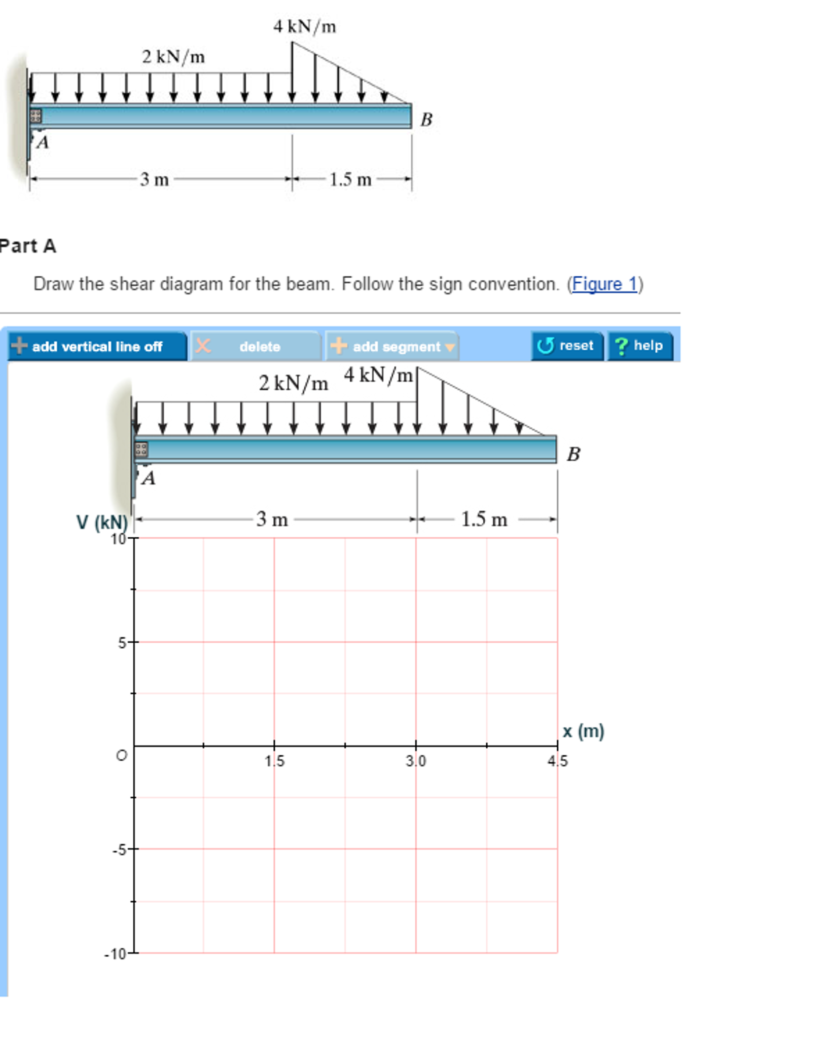
Part A Draw the shear diagram for the beam. Follow the ...
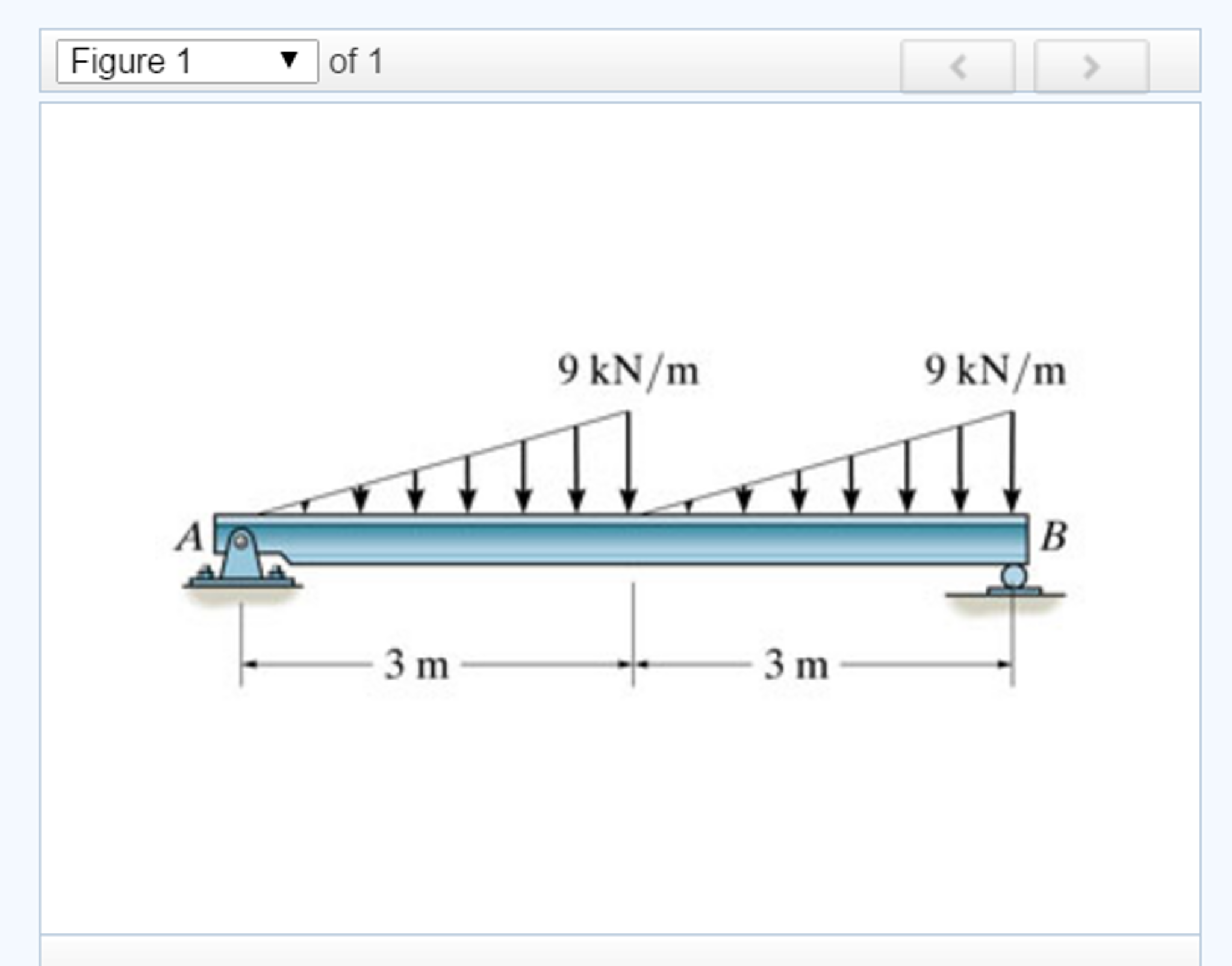
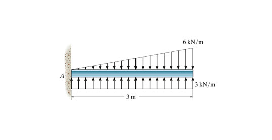
And 2 draw the shear force and bending moment diagrams. Draw the shear diagram for the beam follow the sign convention figure 1. Figure 1 click on add vertical line off to add discontinuity lines. Show transcribed image text problem 770 draw the shear diagram for the beam. Neglect the weight of the beam.
Solved: Draw The Shear Diagram For The Beam. Follow The Si ...
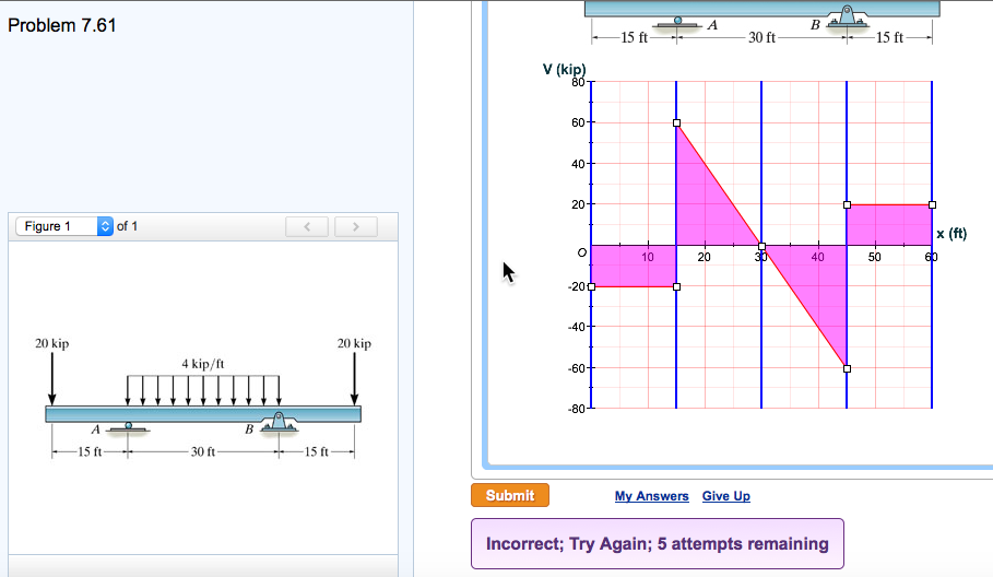
Question: Problem 7.61 Part A Draw the shear diagram for the beam. Follow the sign convention. (Figure 1) Click on "add vertical line off" to add discontinuity lines. Then click on "add segment" button to add functions between the lines. Note 1 - You should not draw an "extra" discontinuity line at the point where the curve passes the x-axis.
Solved: A) Draw The Shear Diagram For The Beam. Follow The ...
Jul 07, 2021 · Draw the shear diagram for the beam follow the sign convention. And 2 draw the shear force and bending moment diagrams. Assume the support at is a pin. Figure 1 click on add vertical line off to add discontinuity lines. Shear force and bending moment and also some basic concepts of strength of materials in our recent posts.

“Whatever it takes†sign
Nov 19, 2021 · General sign conventions for bending moment: The bending moment at a section is considered as positive when the beam is sagging. The bending moment at a section is considered as negative when the beam is hogging. Step-by-step Step 1 of 3. Draw the free body diagram of the beam as shown in Figure (2).

Solved: Draw The Shear Diagram For The Beam. Follow The Si ...
booklet follow the above sign convention. In drawing the shear force diagram and bending moment diagrams various sign conventions are used by different authors. The following sign convention is adopted in this booklet and the flexure formula needs to be interpreted based on this sign convention. Force or moment in the
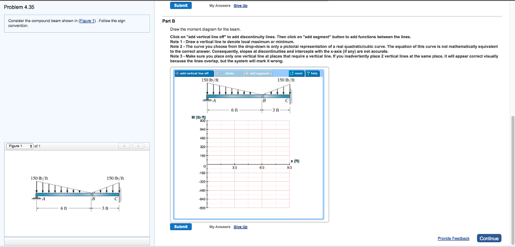
Solved: Consider The Compound Beam Shown In (Figure 1) . F ...
Part A Draw the shear diagram for the beam. Follow the sign convention. Click on the ~'add vertical line off~' to add discontinuity lines. Then click …
34 Draw The Moment Diagram For The Beam. Follow The Sign ...
17.5.2018 · Sign Convention for shear force F F F F + ve shear force - ve shear force 8. Sign convention for bending moments: The bending moment is considered as Sagging Bending Moment if it tends to bend the beam to a curvature having convexity at the bottom as shown in the Fig. given below. Sagging Bending Moment is considered as positive bending moment.
Solved: A. Draw The Shear Diagram For The Beam. Follow The ...
17.10.2021 · 1. The moment diagram is a straight, sloped line for distances along the beam with no applied load. The slope of the line is equal to the value of the shear 2. Udl results in a parabolic curve on the moment diagram. 3. The max/min values of moment occur where the shear line crosses zero. 4.
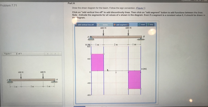
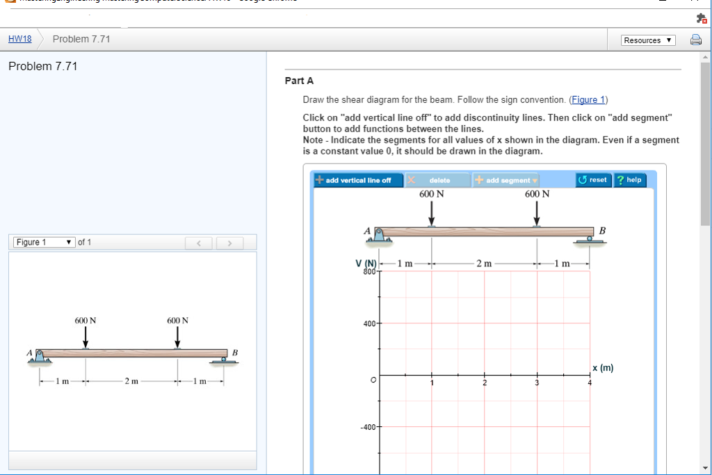
Solved: Part A Problem 7.71 Draw The Shear Diagram For The ...
Answer: As long as you are consistent it does not really matter which you consider positive and which you consider negative. To fall in line with general practice I recommend you consider sagging moment as positive and hogging moment as negative. Draw the BM diagram consistently on the tension ...

27 Draw The Moment Diagram For The Beam Follow The Sign ...
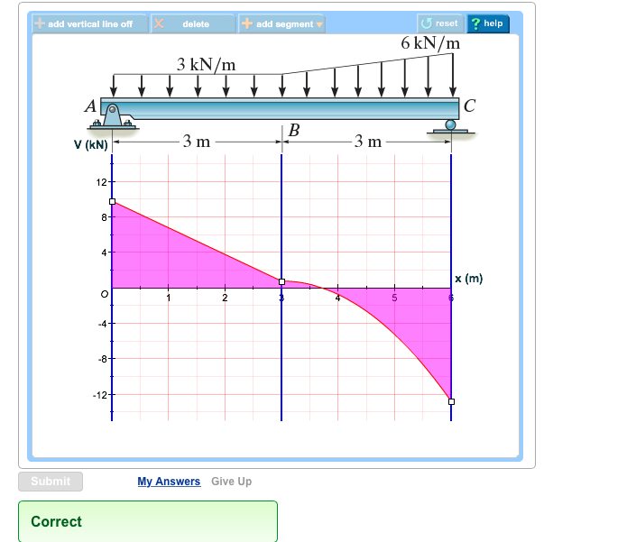
Draw the moment diagram for the beam. Follow the sign convention. Click on "add vertical line off" to add discontinuity lines. Then click on "add segment" button to add functions between the lines. Note 1- Make sure you place only one vertical line at places that require a vertical line.
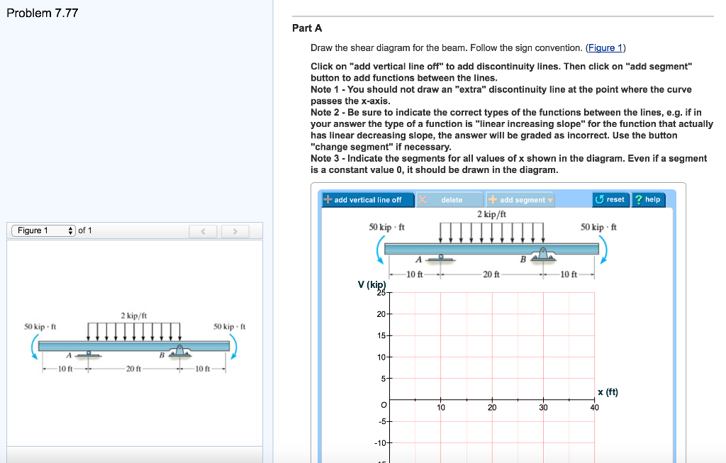
Solved: Problem 7.77 Part A Draw The Shear Diagram For The ...
beam from the left hand end and summing up the areas of shear force diagrams using proper sign convention. xThe process of obtaining the moment diagram from the shear force diagram by summation is exactly the same as that for drawing shear force diagram from load diagram.
Solved: Draw The Shear Diagram For The Beam. Follow The Si ...

For the Figure below, determine: Part A Draw the shear ...
29 Draw The Shear Diagram For The Beam. Follow The Sign ...
Solved: Draw The Shear Diagram For The Beam. Follow The Si ...
Solved: Draw The Shear Diagram For The Beam. Follow The Si ...
Solved: Draw The Shear Diagram For The Beam. Follow The Si ...
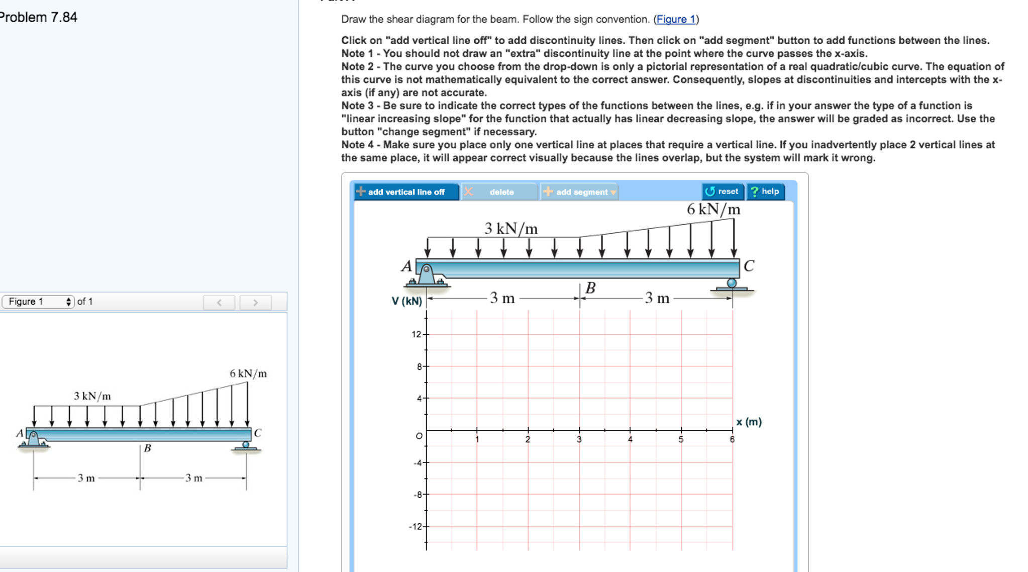
Draw the shear diagram for the beam. Follow the sign ...

Solved: Problem 7.92 1of1 ? V Complete Draw The Moment Dia ...
Solved: Part A Draw The Shear Diagram For The Beam. Follow ...

Solved: Draw The Shear Force And Moment Diagrams For The B ...
Solved: Draw The Shear Diagram For The Beam. Follow The Si ...
Draw The Moment Diagram For The Beam Follow The Sign ...

PART A Draw the shear diagram for the beam. Follow the ...
Need Part B: Draw the moment diagram for the | Chegg.com
Solved: Draw The Moment Diagram For The Beam. Follow The S ...

Draw the moment diagram for the beam as shown. Follow the ...
Solved: Part A Draw The Shear Diagram For The Beam. Follow ...
Solved: Draw The Shear Diagram For The Beam. Follow The Si ...
Solved: Problem 7.81 Part B Draw The Moment Diagram For Th ...
Solved: A) Draw The Shear Diagram For The Beam. Follow The ...

Still Awesome | Instagram: @timmossholder

For the figure below, draw: a) Draw the shear diagram for ...
Solved: Part A - Draw The Shear Diagram For The Beam. Foll ...
0 Response to "42 draw the moment diagram for the beam. follow the sign convention."
Post a Comment