40 moment diagram for cantilever beam
Draw the shear force and bending moment diagrams for the cantilever beam supporting a concentrated load of 5 lb at the free end 3 ft from the wall. 1. Draw a FBD of the structure . 2. Calculate the reactions using the equilibrium equations (may not need to do this if choosing a cantilever beam and using the free side for the FBD). Cantilever beam calculation example. x
Once you have the reactions, draw your Free Body Diagram and Shear Force Diagram underneath the beam. Finally calculating the moments can be done in the following steps: 2. From left to right, make "cuts" before and after each reaction/load. To calculate the bending moment of a beam, we must work in the same way we did for the Shear Force ...

Moment diagram for cantilever beam
3.2 - Shear Force & Bending Moment Diagrams What if we sectioned the beam and exposed internal forces and moments. This exposes the internal Normal Force Shear Force Bending Moment ! What if we performed many section at ifferent values Of x, we will be able to plot the internal forces and bending moments, N(x), V(x), M(x) as a function Of position! 06.01.2005 · BEAM DESIGN FORMULAS WITH SHEAR AND MOMENT DIAGRAMS American Forest & Paper Association w R V V 2 2 Shear M max Moment x DESIGN AID No. 6. AMERICAN WOOD COUNCIL The American Wood Council (AWC) is part of the wood products group of the American Forest & Paper Association (AF&PA). AF&PA is the national trade association of the … Moment diagram by parts can be drawn in different ways; three are shown below. 111 1st Solution: 2nd Solution: 112 Example 4.7 For the beam loaded as shown in Fig. E4.7, compute the moment of area of the M diagrams between the reactions about both the left and the right reaction. (Hint: Draw the moment diagram by parts from right to left.) Figure E4.7 . 113 . 114 …
Moment diagram for cantilever beam. M = bending moment (Nm, lb in) I = moment of Inertia (m4, mm4, in4) The maximum moment in a cantilever beam is at the fixed point and the maximum stress can be calculated by combining 1b and 1d to σmax = ymax F L / I (1e) Example - Cantilever Beam with Single Load at the End, Metric Units Cantilever Beam Moment Diagram. bending moment of a cantilever beam i assumed the mass was distributed uniformly along the beam i don t know how i would draw the shear force and moment diagram in this case since the force calculator for bending moment and shear force for cantilever free online calculator for civil and mechanical engineers to determine bending moment and shear force values for ... What is the bending moment diagram? What is the moment of cantilever beam? In a cantilever beam, shear force at any section is equal to the sum of the loads between the sections and the free end. 12.08.2016 · directly on the diagram. Pertinent dimensions may also be represented for convenience. Note, however, that the free-body diagram serves the purpose of focusing accurate attention on the action of the external forces; therefore, the diagram should not be cluttered with excessive information. Force arrows
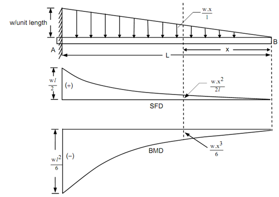
Chapter-4 Bending Moment and Shear Force Diagram S K Mondal's Maximum bending moment, 2 max wL 2 M at fixed end Another way to describe a cantilever beam with uniformly distributed load (UDL) over it's whole length. (iii) A Cantilever beam loaded as shown below draw its S.F and B.M diagram In the region 0 < x < a Answer: Bending Moment diagram of a Cantilever subjected to uniformly varying load: Consider a cantilever beam of length L subjected to uniformly varying load or triangular load w N/m throughout its length as shown in figure. Uniformly varying load is distributed over the entire span or part of... Shear Force and Bending Moment Diagram of Cantilever beam when point load is applied From the figure we have the value of load at point A and point B. So let's draws the shear force diagram with the help of these loading. Bending moment at point A is zero. Bending moment at point B= -2*2 = 4 KN-M Bending moment at point C= -2*4-4*2 = 12 KN-M The bending moment diagram of a cantilever beam with a uniform distributed load is given in the following figure. The curve is parabolic, with zero slope at point B. The fixed support of the cantilever beam enforces zero deflection and slope at point A. A sketch of a the deflected is first drawn. ...
Cantilever Beam Free Body diagram Cantilever Beam Boundary conditions Determine the internal shear and Bending moment in the cantilevered beam as a function of x Finding Shear force and Bending Moment acting at a distance of 2 m from the free end on a Cantilever beam with Uniformly Distributed load (U.D.L.) A bending moment diagram is the graphical representation of the variation of he bending moment along the length of the beam and is abbreviated as B.M.D. We will take different cases of beams and loading for plotting S.F. D and B.M.D. Cantilever : Point Load at the End (Fig. 3.8) basics of shear force and bending moment diagrams and sign conventions for shear force and bending moment in our recent posts. We have also discussed the concept to draw shear force and bending moment diagrams for a cantilever beam with a point load during our previous posts. Cantilever Beam Loaded By A Bending Moment At Its End As Seen From Scientific Diagram. Q1 Draw The Shear Force And Bending Moment Diagrams Chegg. Bending Moment And Shear Force Diagram For Cantilever. Cantilever Beam Point Load At Any. A Cantilever Beam With Varying Section Under Scientific Diagram. Beam Formulas With Shear And Mom.
Solved: Draw The Shear And Moment Diagrams For The Cantile ...
BEAM DIAGRAMS AND FORMULAS 3-219 Table 3-23 (continued) Shears, Moments and Deflections 18. CANTILEVERED BEAM- LOAD INCREASING UNIFORMLY TO FIXED END

Triangular Distributed Load Shear And Moment Diagram ...
This video explains how to draw shear force diagram and bending moment diagram with easy steps for a cantilever beam loaded with a concentrated load. Shear f...

Shear Force Diagram and Bending Moment Diagram for ...
Many structures can be approximated as a straight beam or as a collection of straight beams. For this reason, the analysis of stresses and deflections in a beam is an important and useful topic. This section covers shear force and bending moment in beams, shear and moment diagrams, stresses in beams, and a table of common beam deflection formulas.
What is the bending moment diagram of a cantilever ...
Calculation Example – Torsional moment-Stress. Calculation Example – Reinforced Concrete Column at Stress. Calculation Example – Cantilever Beam with uniform loading. Calculation Example – Cantilever Beam with point loads. Calculation Example – Rod loading Calculation Example – Maximum Deflection Calculation Example – Member Diagram.

Blaydon Railway Bridge, Newcastle/Gateshead, Tyne & Wear, England.
Problem 410 Cantilever beam carrying the uniformly varying load shown in Fig. P-410. [collapse collapsed title="Click here to read or hide the general instruction"]Write shear and moment equations for the beams in the following problems. In each problem, let x be the distance measured from left end of the beam. Also, draw shear and moment diagrams, specifying values at all

Bending Moment Diagram Cantilever Beam — UNTPIKAPPS
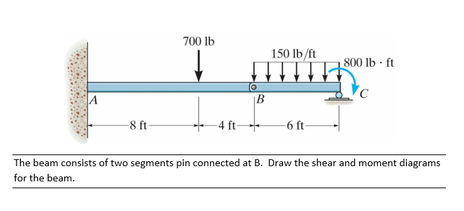
moment for each segment of the beam. (2) Sketch the shear force and bending moment diagrams. Neglect the weight of the beam. Note that the support reactions at A and D have been computed and are shown in Fig. (a). Solution Part 1 The determination of the expressions for V and M for each of the three beam segments (AB,BC, and CD) is explained below.
What is the bending moment diagram of a cantilever ...
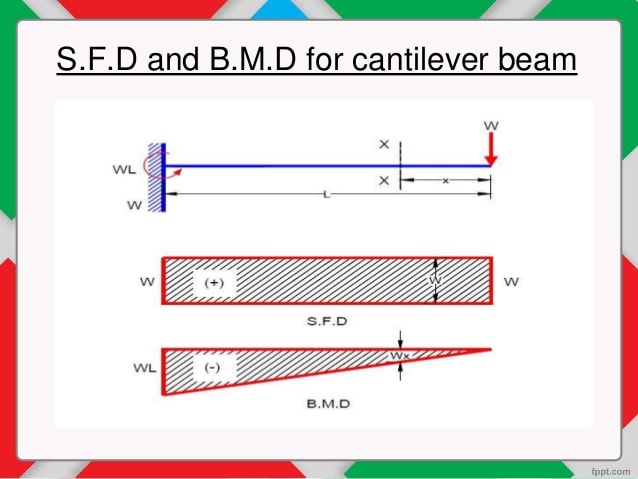
Shear Force (SF) and Bending Moment (BM) Diagram of Cantilever Beam. The shear force at any section of a cantilever beam is the sum of loads between the section and the free end. The bending moment at a given section of a cantilever beam is the sum of moments about the section of all the loads acting between the section and the free end.

Civil Engineering: Shear Force and Bending Moment diagram ...
Generally, in the case of cantilevers, the shear force and the bending moment will be maximum at the supports. In this case the shear force is constant throughout the length of the cantilever. Maximum S.F = +W = +12kN. Cantilever beam shear force diagram. Maximum B.M = -WL = -12 x 4 = -48kN.m.
What is the difference between Continuous Cantilever and ...
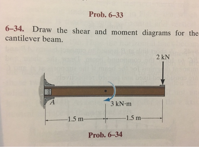
Cantilever beam with point moment. In this case, a moment is imposed in a single point of the beam, anywhere across the span. In practical terms, it could be a force couple, or a member in torsion, connected out of plane and perpendicular to the beam.

Shear Force & Bending Moment with Triangular Load on Beam ...
Shear and moment diagram for a simply supported beam with a concentrated load at mid-span. In solid mechanics , a bending moment is the reaction induced in a structural element when an external force or moment is applied to the element, causing the element to bend .

"Mother I feel you under my feet, Mother I hear your heartbeat.
The bending moment at the two ends of the simply supported beam and at the free end of a cantilever will be zero. Shear force and Bending moment Diagram for a Cantilever beam with a Point load at the free end Shear force and Bending moment Diagram for a Cantilever beam with a Uniformly distributed load
31 Draw The Free Body Diagram For The Cantilevered Beam. A ...
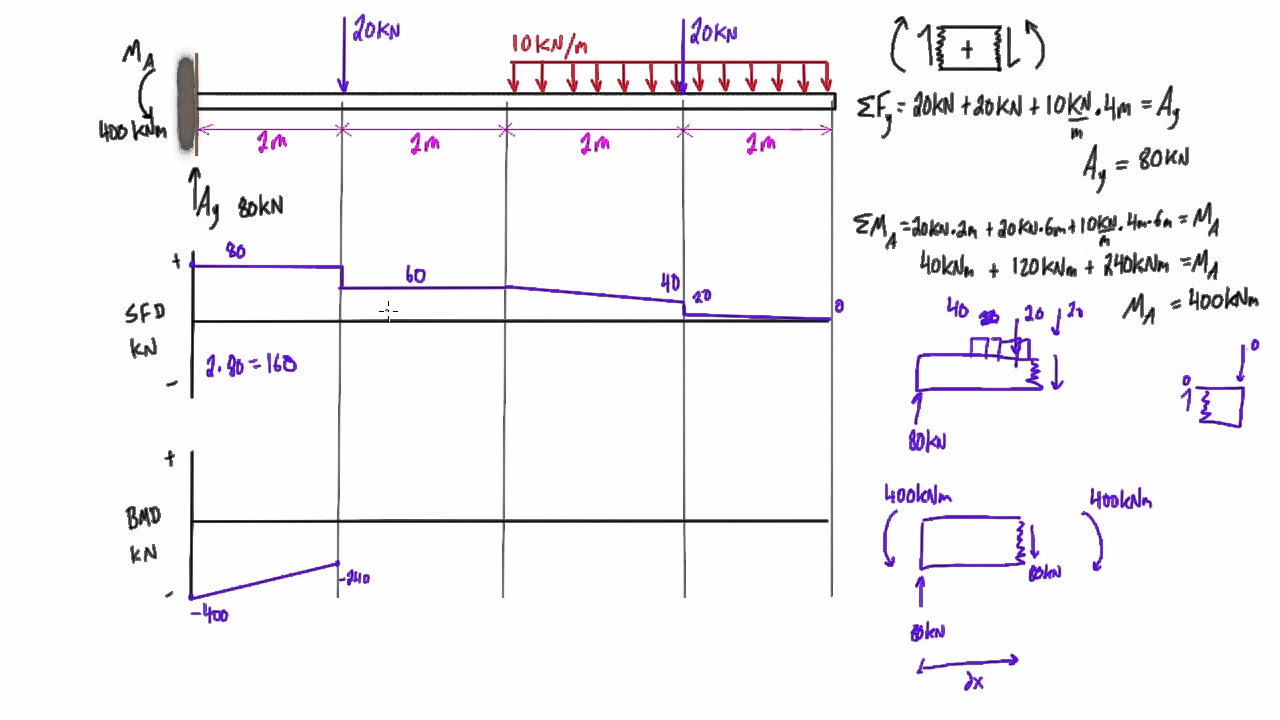
Calculating Shear Force Diagram – Step 2: Keep moving across the beam, stopping at every load that acts on the beam. When you get to a load, add to the Shear Force Diagram by the amount of the force. In this case we have come to a negative 20kN force, so we will minus 20kN from the existing 10kN. i.e. 10kN – 20kN = -10kN.
How To Draw Shear Force And Bending Moment Diagram Of ...
Calculation Example – Torsional moment-Stress. Calculation Example – Reinforced Concrete Column at Stress. Calculation Example – Cantilever Beam with uniform loading. Calculation Example – Cantilever Beam with point loads. Calculation Example – Rod loading Calculation Example – Maximum Deflection Calculation Example – Member Diagram.

Cantilever Beams and Continuous Beams
Cantilever beams moments and deflections shear force bending moment diagram of fixed beam bending moment calculator beam stress deflection mechanicalc shear force bending moment diagram of. Beams Fixed At Both Ends Continuous And Point Lo.
Solved: Draw The Shear And Moment Diagrams For The Cantile ...
This video shows the shear force and bending moment diagram of a cantilever beam with triangular load. A cantilever beam is a type of beam with fixed support...
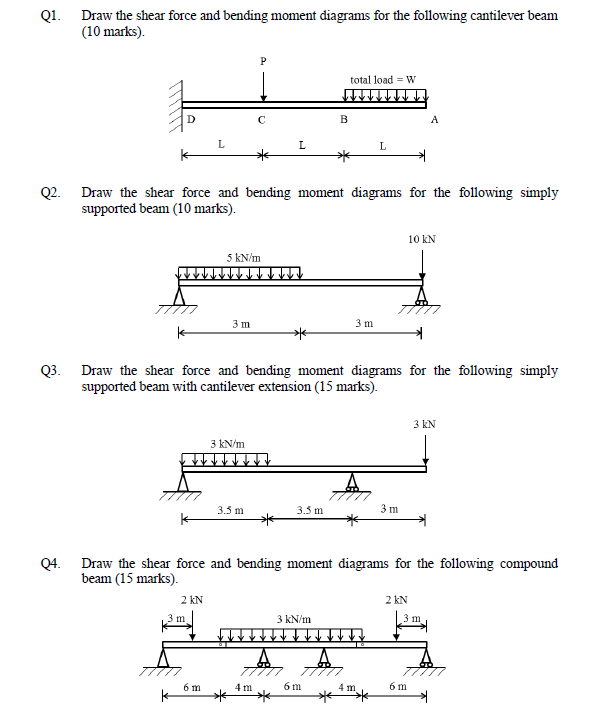
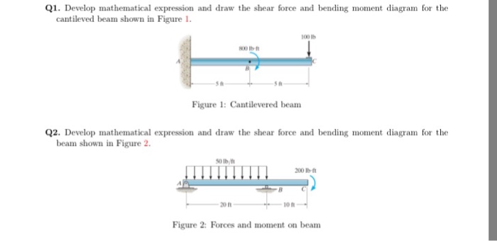
Solved: Q1. Draw The Shear Force And Bending Moment Diagra ...
May 17, 2018 · Draw shear force and bending moment diagrams [SFD and BMD] for beam. Also determine maximum hogging bending moment. 30N/m 4m [Ans: Max. Hogging bending moment = 735 kNm] Exercise Problems 4m3m VM-79 80. 5kN 8. A cantilever beam of span 6m is subjected to three point loads at 1/3rd points as shown in the Fig. given below.
Solved: Draw The Shear Force And Bending Moment Diagram Of ...
Free online beam calculator for generating the reactions, calculating the deflection of a steel or wood beam, drawing the shear and moment diagrams for the beam. This is the free version of our full SkyCiv Beam Software. This can be accessed under any of our Paid Accounts, which also includes a full structural analysis software.
Cantilever Along A Gradually Varying Load, Shear Force and ...
Cantilever Beam I Consider a mass mounted on the end of a cantilever beam. Assume that the end-mass is much greater than the mass of the beam. Figure A-1. E is the modulus of elasticity. I is the area moment of inertia. L is the length. g is gravity. m is the mass. The free-body diagram of the system is Figure A-2. R is the reaction force. M R

Places To Be , Hamburg
and moment diagrams with accompanying formulas for design of beams under various static loading conditions. Shear and moment diagrams and formulas are excerpted from the Western Woods Use Book, 4th edition, and are provided herein as a courtesy of Western Wood Products Association. Introduction Notations Relative to "Shear and Moment Diagrams"

16. Cantilever beam loaded by a bending moment. | Download ...
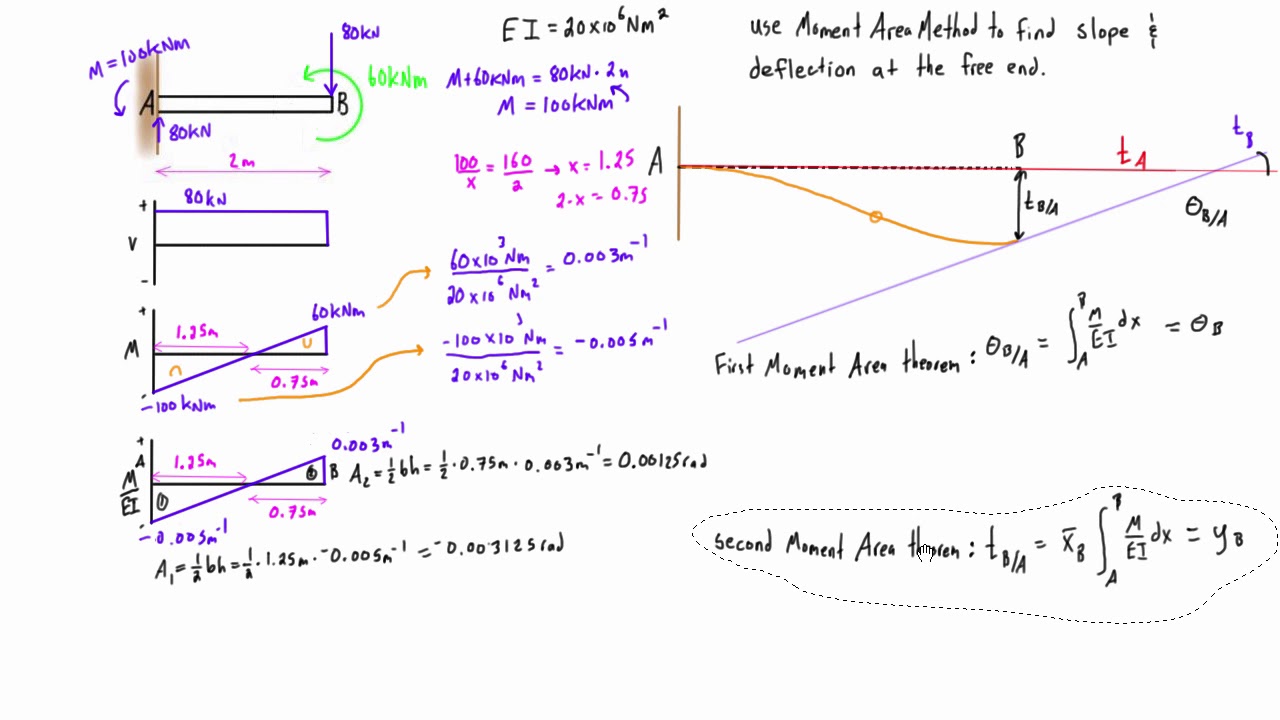
Theorem II The deviation of any point B relative to the tangent drawn to the elastic curve at any other point A, in a direction perpendicular to the original position of the beam, is equal to the product of 1/EI multiplied by the moment of an area about B of that part of the moment diagram between points A and B.

The design scheme of the nib as a cantilever beam with a ...
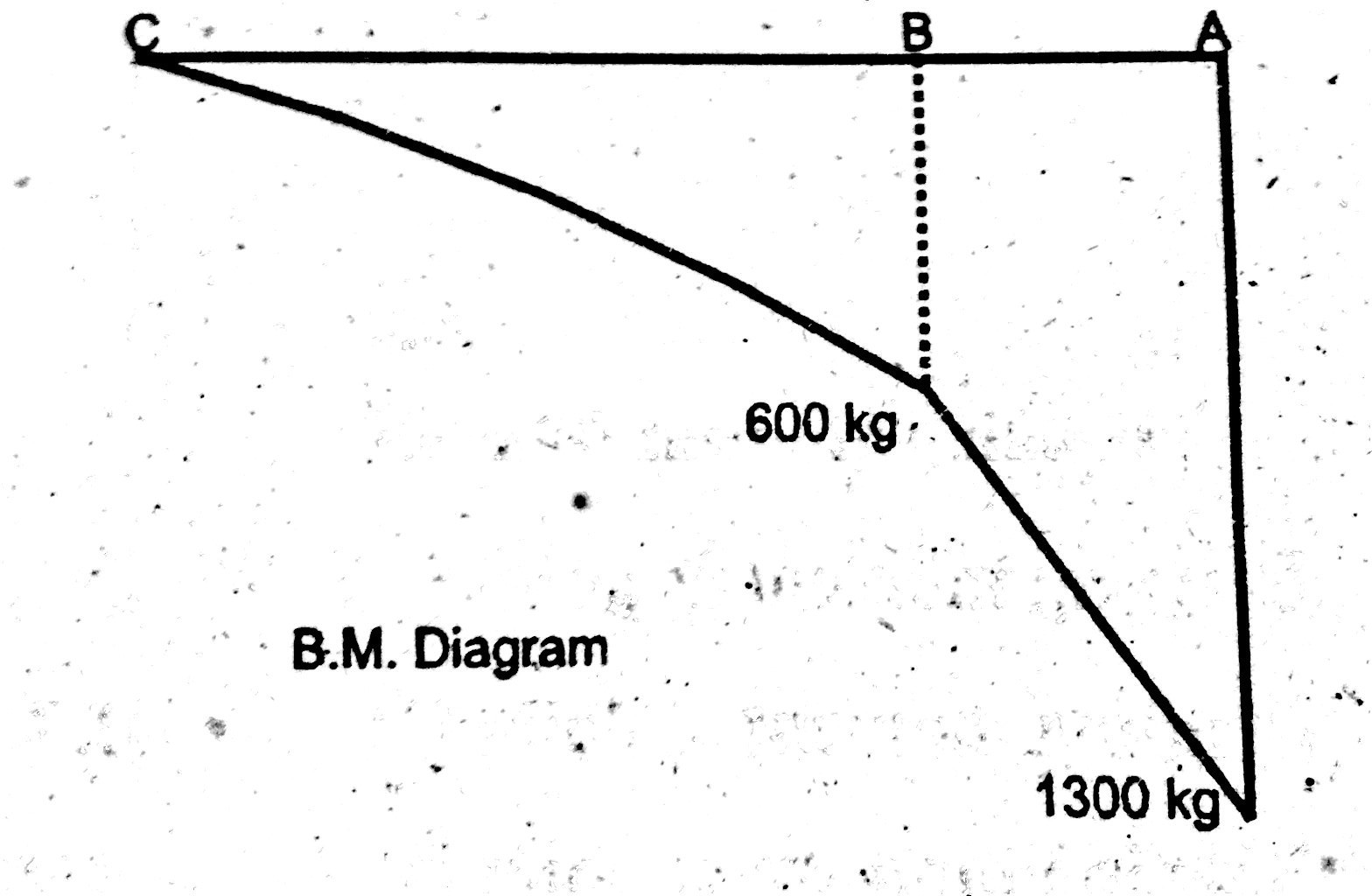
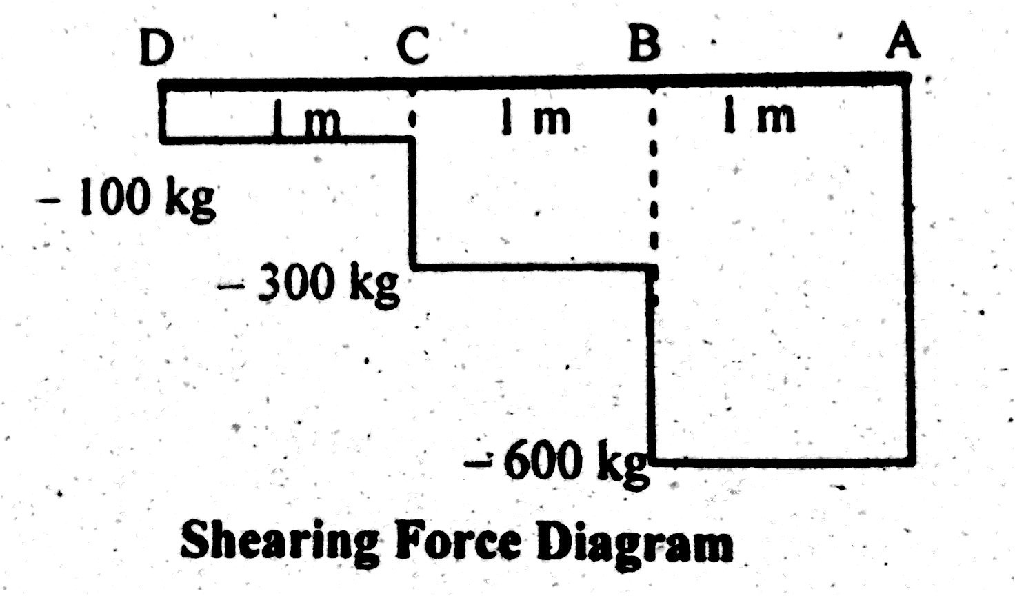
This shows shear force is maximum at fixed end and minimum at free end of cantilever beam. Shear Force Diagram Bending Moment Bending moment at point D = B.M (D) = 0 Bending moment at point C = B.M (C) = - (100×1) = -100 kg.m Bending moment at point B = B.M (B) = - (100×2 +200×1) B.M (B) = -400 kg.m
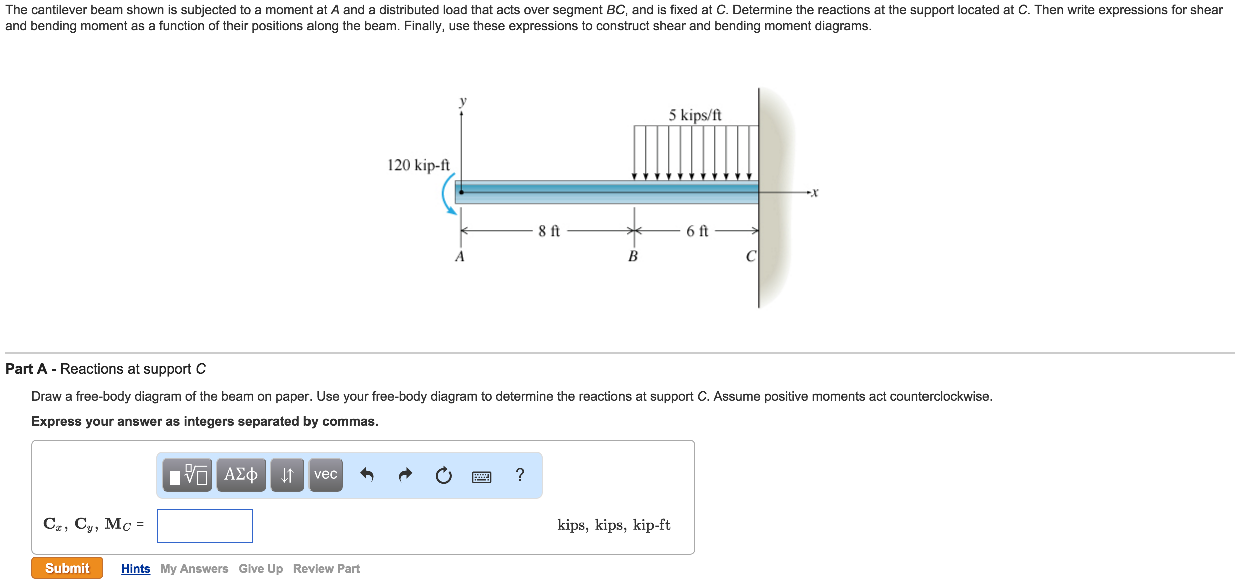
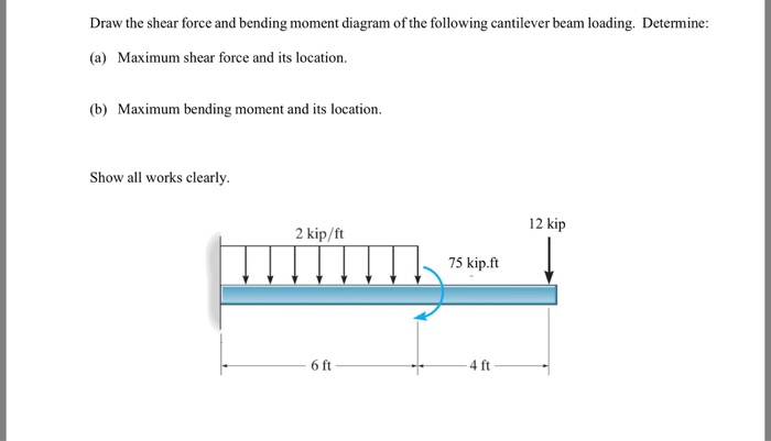
Solved: The Cantilever Beam Shown Is Subjected To A Moment ...
Reinforced Concrete Cantilever Retaining Wall Analysis and Design (ACI 318-14) Reinforced concrete cantilever retaining walls consist of a relatively thin stem and a base slab.
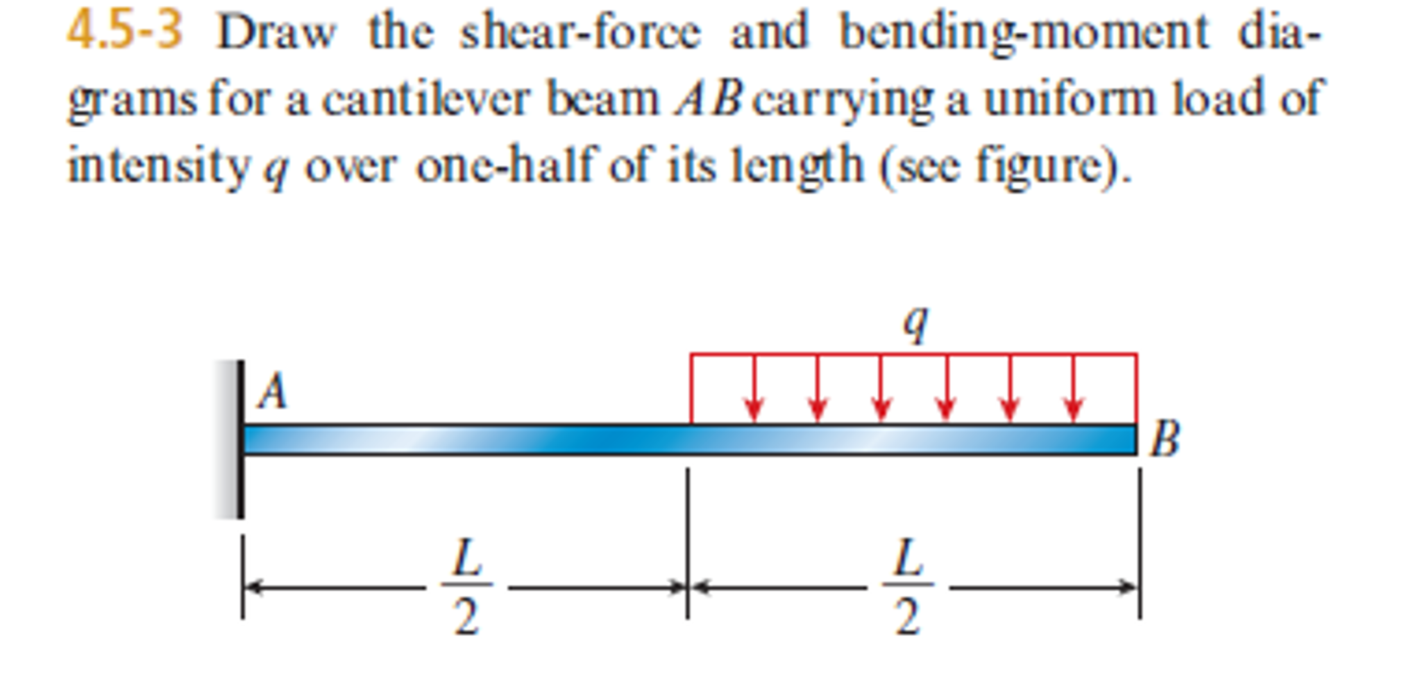
Solved: Draw The Shear-force And Bending-moment Diagrams F ...
Variation of shear force and bending moment diagrams S.N Point Load UDL UVL Shear Force Constant Linear Parabolic Bending Moment Linear parabolic Cubic WORKED EXAMPLES 1) A cantilever beam of length 2 m carries the point loads as shown in Fig. Draw the shear force and B.M. diagrams for the cantilever beam. Shear Force Diagram S.F. at D, F D
Double Cantilever Beam Moment Equation - Tessshebaylo
Moment diagram by parts can be drawn in different ways; three are shown below. 111 1st Solution: 2nd Solution: 112 Example 4.7 For the beam loaded as shown in Fig. E4.7, compute the moment of area of the M diagrams between the reactions about both the left and the right reaction. (Hint: Draw the moment diagram by parts from right to left.) Figure E4.7 . 113 . 114 …

Monochrome, Scotswood Bridge, Tyne & Wear, England.
06.01.2005 · BEAM DESIGN FORMULAS WITH SHEAR AND MOMENT DIAGRAMS American Forest & Paper Association w R V V 2 2 Shear M max Moment x DESIGN AID No. 6. AMERICAN WOOD COUNCIL The American Wood Council (AWC) is part of the wood products group of the American Forest & Paper Association (AF&PA). AF&PA is the national trade association of the …
How to Draw Shear Force & Bending Moment of Cantilever ...
3.2 - Shear Force & Bending Moment Diagrams What if we sectioned the beam and exposed internal forces and moments. This exposes the internal Normal Force Shear Force Bending Moment ! What if we performed many section at ifferent values Of x, we will be able to plot the internal forces and bending moments, N(x), V(x), M(x) as a function Of position!

SHEAR FORCE AND BENDING MOMENT DIAGRAM FOR CANTILEVER BEAM ...

Scotswood Bridge, Newcastle/Gateshead, Tyne & Wear, England.

Shear Force and Bending Moment Diagram for Cantilever Beam ...
Shear Force & Bending Moment Diagram of Cantilever Beam ...

Old Railway Bridge, Newcastle/Gateshead, Tyne & Wear, England.

Scotswood Bridge, Newcastle/Gateshead, Tyne & Wear, England.

PORTRAITS INSTAGRAM - @LGNWVRPRTRTS EDITORIAL INSTAGRAM - @LGNWVRPHTO PERSONAL INSTAGRAM - @LGNWVR

Moment Diagrams Constructed by the Method of Superposition ...
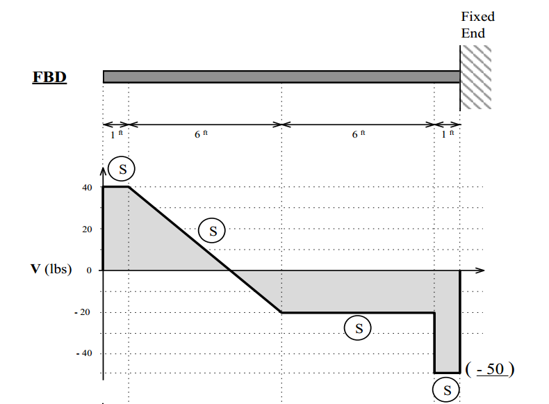
Solved: The Shear Diagram For A Cantilever Beam, Fixed At ...
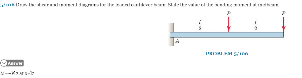
Solved: 5/106 Draw The Shear And Moment Diagrams For The L ...
Solved: Draw The Shear And Moment Diagrams For The Cantile ...
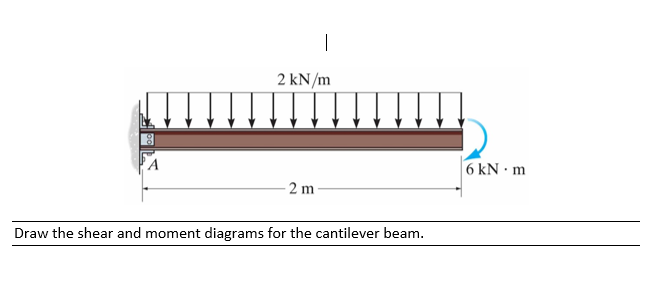
Solved: Develop Mathematical Expression And Draw The Shear ...

Draw The Shear Force And Bending Moment Diagrams For A ...

Overhead Road Bridge, Newcastle/Gateshead, Tyne & Wear, England.
0 Response to "40 moment diagram for cantilever beam"
Post a Comment