40 in a state machine diagram, a state is represented by a(n) _______.
truncated to simply state machine. The current state is a function of past states, and thus the state machine must have memory of its past. A state machine can be represented by a state diagram and/or state transition tables. A counter is a type of state machine. It constantly increases its output value as it sequences finite state machines (FSMs) In chapter 6, we looked at counters, whose values are useful for representing states. Normally the number of states is finite. And a circuit or a system is modeled as a machine that makes transitions among states. The state is the main theme of this chapter.
A classic form of state diagram for a finite automaton (FA) is a directed graph with the following elements (Q, Σ, Z, δ, q 0, F):. Vertices Q: a finite set of states, normally represented by circles and labeled with unique designator symbols or words written inside them; Input symbols Σ: a finite collection of input symbols or designators; Output symbols Z: a finite collection of output ...

In a state machine diagram, a state is represented by a(n) _______.
Figure 10.2 Notation for a state. 10.2.1 State diagram A state diagram consists of nodes, which are drawn as circles (also known as bubbles), and one-direction transition arcs. The notation for nodes and arcs is shown in Figure 10.2. A node represents a unique state of the FSM and it has a unique symbolic name. An arc Here are a few state machines, to give you an idea of the kind of systems we are considering. • A tick-tock machine that generates the sequence 1,0,1,0, . . . is a finite-state machine that ig nores its input. • The controller for a digital watch is a more complicated finite-state machine: it transduces a d) 2n ,where n is no.of flipflops . Q9. The no.of directed arcs terminating on any state of a state diagram is. a) 2n ,where n is no.of inputs. b) 2n ,where n is no.of flipflops in the circuits. c) Independent of no.of inputs. d) Dependent of no.of outputs . Q10. The ___node_____of the state diagram represents the states of the machine. a) Node ...
In a state machine diagram, a state is represented by a(n) _______.. State Machine Diagrams. State machine diagram is a behavior diagram which shows discrete behavior of a part of designed system through finite state transitions. State machine diagrams can also be used to express the usage protocol of part of a system. Two kinds of state machines defined in UML 2.4 are . behavioral state machine, and; protocol state machine In a state-machine diagram when one state is high-level in that it contains other states of an object, it is called a(n) ______. composite state. Rating: 5 · 1 review STATE DIAGRAMS ELEMENTS OF DIAGRAMS FINITE STATE MACHINES •STATE MACHINES-INTRODUCTION-MEALY & MOORE MACH.-SYNC. & ASYNC SYSTEMS • A state diagram represents a finite state machine (FSM) and contains • Circles: represent the machine states • Labelled with a binary encoded number or reflecting state. State Machine Design • Coming up with a state diagram is non-trivial • Requires creative solutions • Designing the circuit from the state diagram is done according to a simple set of steps • To come up w/ a state diagram to solve a problem - Write out an algorithm or series of steps to solve the problem
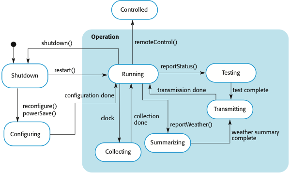
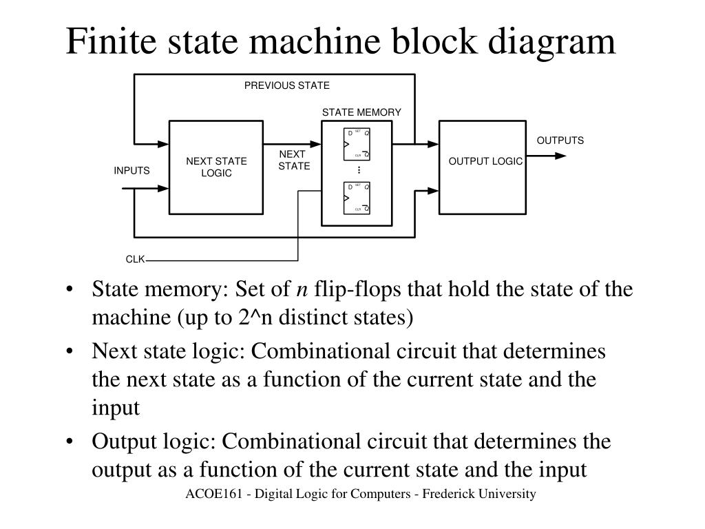
The following diagram illustrates the use of history states. The example is a state machine belonging to a washing machine. In this state machine, when a washing machine is running, it will progress from "Washing" through "Rinsing" to "Spinning". If there is a power cut, the washing machine will stop running and will go to the "Power Off" state. Figure 1 presents an example state machine diagram for the Seminar class during registration. The rounded rectangles represent states: you see that ... Electronic System Design Finite State Machine Nurul Hazlina 8 Can any sequential system be represented with a state diagram? • Shift register -input value shown on transition arcs -output values shown within state node 100 110 111 011 000 010 101 001 1 1 1 1 0 0 0 0 1 This diagram indicates that there is a set of n flip flops that represent the state. There is also some logic that uses the output of the flip flops and the inputs to the system to determine the next state.
- A binary number can represent 2n states, where n is the number of bits. - The number of bits required is determined by the number of states. Ex. 4 states requires 2 bits (22 = 4 possible states) Ex. 19 states requires 5 bits (25 = 32 possible states) - One flip-flop is required per state bit. Steps to Design Sequential Circuits: 1) Draw a ... State Machine Diagram. In State Machines the vertices represent states of an object in a class and edges represent occurrences of events. The additional notations capture how activities are coordinated. Objects have behaviors and states. The state of an object depends on its current activity or condition. Systems Analysis and Design Ch. 4-7. The specific area of the user's business need that is within the scope of the new system is called the _______. One technique to find the "things" that need to be included in the new system begins by starting with a user and the use cases and then try to identify the necessary informational "things." A Finite State Machine can be represented by a transition diagram that shows what states are available and what input values cause a transformation from one state to another. The following transition diagram shows the states named as A, B, and C. The states are defined by the values stored in the registers; ...
Operating System : Process Concept - SciComp
Output rules: \(f(S_i)\) for each of the \(k\) states. State Machine Diagram and the Truth Table. We can represent a state machine in two forms: **state transition diagram or truth table**. Suppose we have a simple digital lock machine, that will open only if we give the password: 0110. The following state diagram illustrates how that lock works:

(PDF) Dynamic synthesis of Heisenberg-limited spin squeezing
This behavior is analyzed and represented as a series of events that can occur in one or more possible states. Hereby "each diagram usually represents objects of a single class and track the different states of its objects through the system". State diagrams can be used to graphically represent finite state machines.
State Machine Tutorial - UML Tutorial
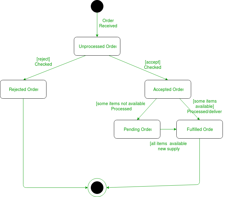
Initial and Final States. The initial state of a state machine diagram, known as an initial pseudo-state, is indicated with a solid circle. A transition from this state will show the first real state The final state of a state machine diagram is shown as concentric circles. An open loop state machine represents an object that may terminate before the system terminates, while a closed loop ...
Wolfram 2,3 Turing Machine Research Prize: Technical Details
There are a total of two types of state machine diagram in UML: 1. Behavioral State Machine Diagram. It captures the behavior of an entity present in the system. It is used to represent the specific implementation of an element. The behavior of a system can be modelled using behavioral state machine diagram in OOAD. 2. Protocol State Machine ...

Define Five state model with Diagram. And also complete ...
State Machine Design • Coming up with a state diagram is non-trivial • Requires creative solutions • Designing the circuit from the state diagram is done according to a simple set of steps • To come up w/ a state diagram to solve a problem - Write out an algorithm or _____ to solve the problem

uml-tutorial-activity-diagram-example in 2021 | Activity ...
A state machine diagram is used to document the states and transitions of a(n) ______.A) Message B) Object C) Business process. D) Use case. B) Object.
Which Statement Correctly Describes The Diagram - Free ...
A state diagram is used to represent the condition of the system or part of the system at finite instances of time. It's a behavioral diagram and it represents the behavior using finite state transitions. State diagrams are also referred to as State machines and State-chart Diagrams.These terms are often used interchangeably. So simply, a state diagram is used to model the dynamic behavior ...

Evolutionary Logic Synthesis of Quantum Finite State ...
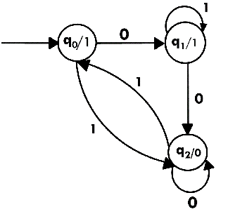
FSM can be described as a state transition diagram. For example, figure 1 depicts state transition diagram where Q = {s 0, s 1} and Σ = {0, 1}. For complex problems, the difficulty in representing the system as FSM is how to deal with the state explosion problem. A system with n variables that can have Z values can have Z n possible states.

Users Guide 5 - PDF Free Download
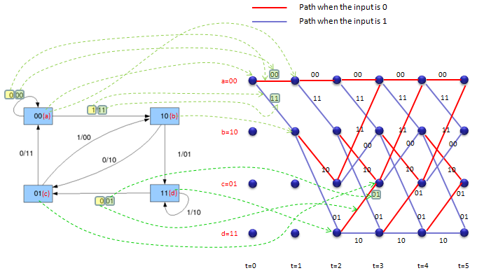
- The state machine is represented as a state transition diagram (or called state diagram) below - One step (i.e., transition) can be taken whenever there is a clock signal State Transition Diagram (or State Diagram) S0 S3 S1 S2 Coover Hall Sweeney Hall Durham Center Parks Library Start 3 • States can be coded as binary combinations of ...
What is a finite-state machine? - Quora
For N states, use ceil(log 2N) bits to encode the state with each state represented by a unique combination of the bits. Tradeoffs: most efficient use of state registers, but requires more complicated combinational logic to detect when in a particular state. Choice #2: "one-hot" encoding For N states, use N bits to encode the state where ...

Suggested diagram to represent the state transitions ...
UML state machine, also known as UML statechart, is an extension of the mathematical concept of a finite automaton in computer science applications as expressed in the Unified Modeling Language (UML) notation.. The concepts behind it are about organizing the way a device, computer program, or other (often technical) process works such that an entity or each of its sub-entities is always in ...
Create a UML activity diagram - Visio
UML state diagram. State machines can be very well represented as a UML state diagram. A UML state diagram describes an automaton that is in exactly one state of a finite set of states at any given time. The states in a UML state diagram are represented by rectangles with rounded corners (vertices) (in other diagram forms also often as a circle).

The finite state machine for level walking. Blocks ...
Spring 2010 CSE370 - XIV - Finite State Machines I 3 Example finite state machine diagram 5 states 8 other transitions between states 6 conditioned by input 1 self-transition (on 0 from 001 to 001) 2 independent of input (to/from 111) 1 reset transition (from all states) to state 100 represents 5 transitions (from each state to 100), one a self-arc
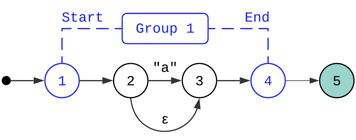
Regex, Part 2: Compiler | kean.blog
d) 2n ,where n is no.of flipflops . Q9. The no.of directed arcs terminating on any state of a state diagram is. a) 2n ,where n is no.of inputs. b) 2n ,where n is no.of flipflops in the circuits. c) Independent of no.of inputs. d) Dependent of no.of outputs . Q10. The ___node_____of the state diagram represents the states of the machine. a) Node ...
CS 410/510 - Software Engineering class notes
Here are a few state machines, to give you an idea of the kind of systems we are considering. • A tick-tock machine that generates the sequence 1,0,1,0, . . . is a finite-state machine that ig nores its input. • The controller for a digital watch is a more complicated finite-state machine: it transduces a

Statechart for air conditioner system | Download ...
Figure 10.2 Notation for a state. 10.2.1 State diagram A state diagram consists of nodes, which are drawn as circles (also known as bubbles), and one-direction transition arcs. The notation for nodes and arcs is shown in Figure 10.2. A node represents a unique state of the FSM and it has a unique symbolic name. An arc
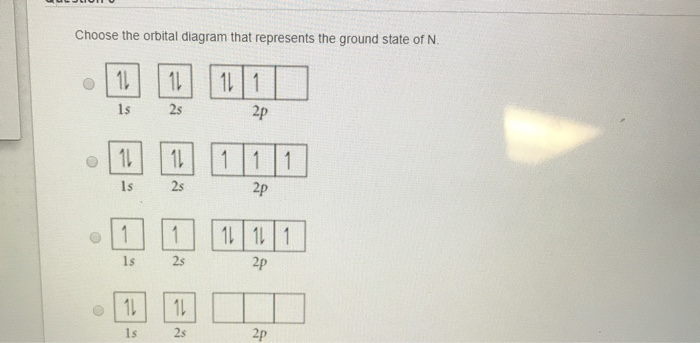
Solved: Choose The Orbital Diagram That Represents The Gro ...
Transition diagram
PPT - FINITE STATE MACHINES (FSMs) PowerPoint Presentation ...
The NSCL production readout software. -- State transition ...
Theory Of Computation

Beach, Maui

Type-Level Finite-State Machines. In this article you get ...

Transition state diagram (n: number of customers present ...
Mealy and Moore Machines - GeeksforGeeks

Akka Finite State Machine (FSM) and At Most Once Semantics ...

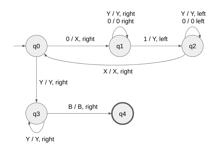
For the state diagram of a Turing machine that | Chegg.com

Predictor finite state machine. Double circles represent ...
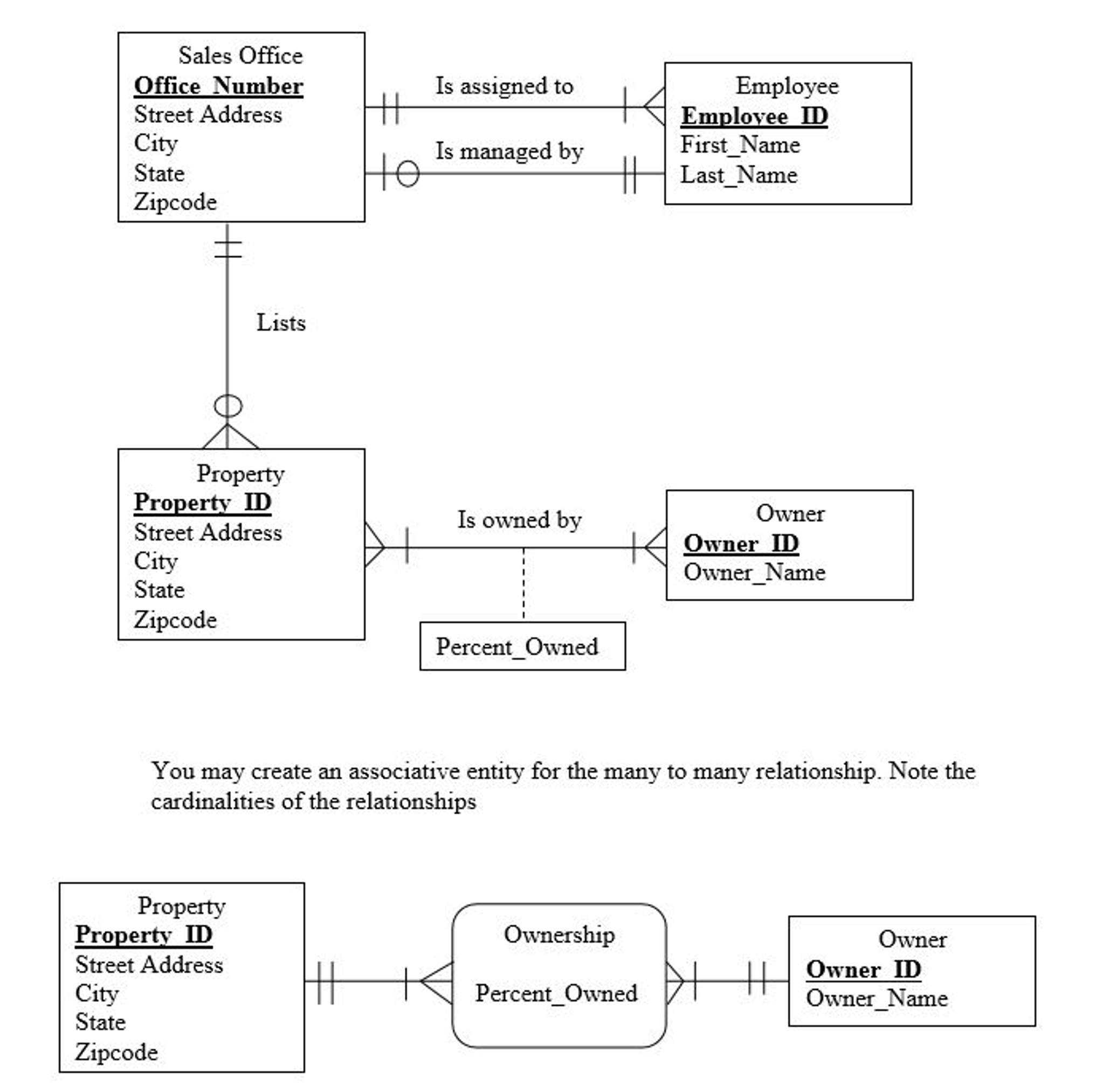
Represent Foreign Key In Er Diagram | ERModelExample.com

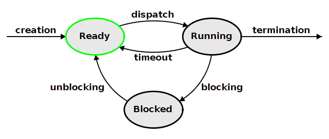
Processes and Threads

Moore machine for Example 2 and n = 3. The state label ...

State Diagram for Online Banking System - GeeksforGeeks
Unified Modeling Language (UML) | State Diagrams ...

State transition diagram. Red and orange lines represent ...
ShareTechnote

Generalized equivalent circuit model of synchronous ...
Automata Moore Machine - Javatpoint


Draw the state diagram for a Mealy state machine with two ...
0 Response to "40 in a state machine diagram, a state is represented by a(n) _______."
Post a Comment