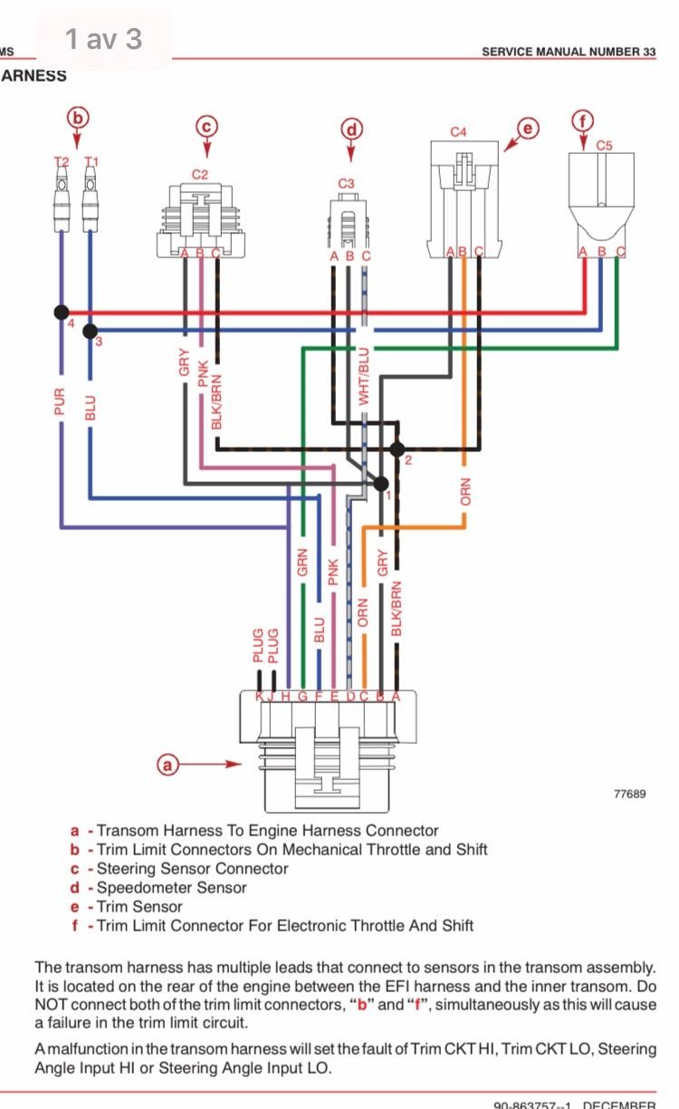
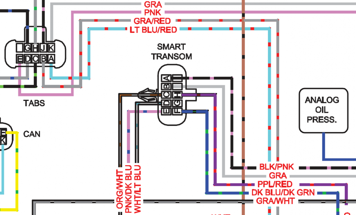
44 mercury trim gauge wiring diagram
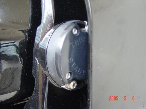
Scroll down to explore all 10 images uploded under Mercruiser Wiring Diagram's gallery . The Trim Sender Switch is used to send a signal to the Trim Gauge so you can see the level of the drive. Description: The Trim Senders are located on either side of the Gimbal Ring. The Trim Limit Switch is mounted to the Port side of the Gimbal Ring.
hi guys ..i need help diagram to wiring my johnson 70 hp seahorse model 1981-gauges. i have a tachometer/fuel sender/tilt trim/ and speed gauges to connect. 1 the switch from commander center 3 wires purple/red/black-2 the connection from relay trim unit-a flat switch with 3 wires =green/blue/red-the are in lead tow extra wiring cables small ...
Omc Trim Gauge Wiring Diagram - wiring diagram is a simplified pleasing pictorial representation of an electrical circuit. It shows the components of the circuit as simplified shapes, and the capacity and signal associates amid the devices. A wiring diagram usually gives suggestion not quite the relative position and contract of devices and ...
Mercury trim gauge wiring diagram
Power Trim Tilt Motor And Wire Harness Kit P N 584107 Crowley Marine. Viewing A Thread 2 Wire Motor Trim Wiring Diagram. Mercury Trim Gauge Mercruiser Outboard Quicksilver 79 895292a01 Gauges Wiring Bottom Line Isle Of Man. I Have A Mercruiser 898r From 1983 The Trim Up Switch Stopped Working Couple Of Years Ago Trailer.
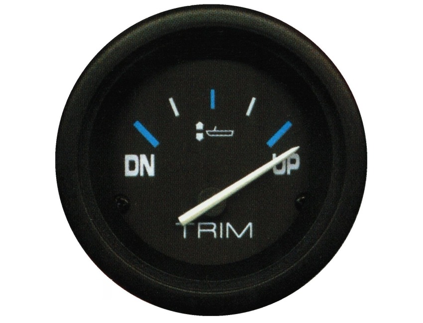
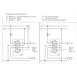
4. Connect a wire to the stud marked "S" (signal) and secure with a nut and lock washer. Connect the other end of the wire to the trim signal terminal or wire. It is recommended that insulated wire terminals, preferably ring type, be used on all connections to the gauge, except the light, which requires a 1/4" female blade terminal. 5.
Files are fully down-loadable and printable . Find great deals on eBay for faria trim gauge mercury. Shop with confidence. Jul 18, · Faria Trim Gauge Wiring Diagram trim gauge is faria instruments have a wire or terminal that provides the trim gauge the trim signal wire or terminal 5 go to next page for diagrams of wire connections.
Mercury trim gauge wiring diagram.
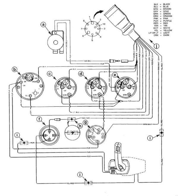
478 WIRING DIAGRAMS Speedometer Tachometer Temperature gauge Trim position gauge Harness connector for Instruments & remote control (to engine) Trim switch Lanyard safety switch Lanyard switch lead Up Dn Instrument/remote control harness connection to engine To engine temp.sender (optional) Ignition key switch Warning horn Instrument harness ...
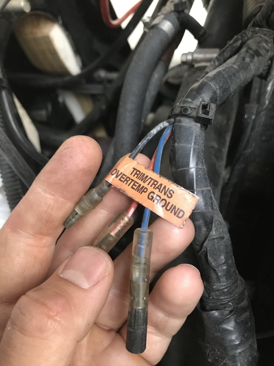
I just purchased a new boat with a 200 HO. The motor has a jet installed and works wonderfully. I am wanting to add a trim gauge to my dash displays. I have a gauge on the way that will work for my motor. However, I need to know what wires from the wiring harness I will need to feed the gauge. I know the motor has a trim transducer.
Mercruiser Trim Sender Wiring Diagram - mercruiser alpha one trim sender wiring diagram, mercruiser digital trim sender wiring diagram, mercruiser trim position sender wiring diagram, Every electrical arrangement is composed of various different pieces. Each part should be placed and connected with different parts in specific way. Otherwise, the structure won't work as it ought to be.
MERCURY WIRING DIAGRAMS. The linked images are printable but may print across more than 1 page (in order to be legible). Most models also have black-&-white-only
WIRING FOR SMARTCRAFT GAUGES 90-879939001 AUGUST 2007 Page 7 / 34 Data Harness Connections: Dual Engine with Dual Helm IMPORTANT: Route wiring harnesses to avoid contact with any sharp edges, hot surfaces, or moving components. Anchor every wiring harness to prevent frictional chafing or cuts. 1.
Suzuki Trim Gauge Wiring Diagram from static-assets. Multi-Function Gauges. Multi-Function Gauges. Easy financing is available just call or email to request an application. Thus, the network is powered on and off by the engine key. IS0003b - Temperature Gauge, Cylinder Head Outboard Motor installation instructions.
Mercury Trim Gauge Wiring Diagram - wiring diagram is a simplified gratifying pictorial representation of an electrical circuit. It shows the components of the circuit as simplified shapes, and the facility and signal friends in the midst of the devices. A wiring diagram usually gives assistance practically the relative point of view and pact ...
IS0100 - Gauge Trouble-shooting Quick Reference Guide for Gauge trouble shooting. Misc. Gauges Help Guide: IS0100 - Gauge Trouble-shooting manual and technical support. Includes Fuel, Pressure, Temperature, Rudder Angle and Trim gauges. Measured Drawings: IS0100 - Measured Drawings for most Faria gauges. Note: Case diameter dimension is panel ...
Suzuki Trim Gauge Wiring Harness 36682 90j00 Marine Surplus. Merc trim gauge wiring electrical questions for e tec rigging moderated mercury mercruiser 2020 f70 la diagram needed the yamaha sender ribnet forums smartcraft offsonly com power tilt motor and wire harness 1998 johnson 115 what sierra arctic series issue hull resistor 2 df50 how to analog conversion faria 12828 mariner limit club ...
The tilt/trim switch on the control has absolutely nothing to do with the tilt/trim gauge. The switch controls the motor that moves the transom bracket. The sensor reads the position of that bracket and sends it back to the gauge. There is only one wire involved. (The return loop from sensor to gauge is via ground).
Belt, Mercury Mercury Relay, Trim Assembly Extension 25\" Models Johnson/Evinrude Seal and Pin. I bought a Yamaha trim gauge to hook up to my Yamaha F40 diagram that shows the connection of devices like the trim gauge.Please review our Warranty, Returns & Refunds policies before you place an order.. DISCLAIMER.
Ebook-9159] Mercruiser Trim Sender Wiring Diagram User Manual | 2019 - Mercruiser Trim Sender Wiring Diagram. You are able to usually rely on Wiring Diagram being an essential reference that can help you preserve time and money. With all the assist of the e-book, you are able to very easily do your own personal wiring assignments.
Color Diagrams Page 8A-6 90-897725 MARCH 2005 75/90 FourStroke EFI Typical Gauges with Tach Signal Converter 1 - Panel Control 4000 2 - Neutral lock button 3 - Trim switch 4 - Throttle only button 5 - Lanyard stop switch 6 - Lanyard stop switch leads must be soldered and covered with shrink tube for a water proof connection.

Universal motorboat digital trim gauge 52mm 0-190 ohm waterproof trim meters for auto truck boat red backlight 9-32v
MERCURY/MARINER COMMON WIRING COLOR CODES : WIRE COLOR(S) FUNCTION: COLOR SAMPLE : BLACK: GROUND: BROWN: Reference Electrode MerCathode System : ORANGE: Anode Electrode MerCathode System : LIGHT BLUE / WHITE STRIPE : Trim UP Switch : LIGHT GREEN / WHITE STRIPE : Trim DOWN Switch : BROWN/WHITE STRIPE : Trim Sender to Trim Gauge : PURPLE / WHITE ...
24. To Remote Control Trim Switch 25. Cowl Mounted Trim Switch 26. Trim Down Relay 27. Trim Up Relay 28. To Trim Pump 29. To 12 Volt Battery 30. Trim Sender 31. Fuel Pump #1 (Inside Vapor Separator) 32. Fuel Pump #2 (Outside Vapor Separator) 33. Engine Harness 34. To Temperature Gauge 35. Low Oil Light 36. Over Heat Light 37. Water in Fuel ...
Mercury Trim Gauge Mercruiser Outboard Quicksilver 79 895292a01 Gauges Wiring Bottom Line Isle Of Man. Tachometer Trim Gauge And Alarm Horn Serial Range Mercury Race Outboard Merc Mar 2 4l Efi 0a168044 Thru 0b290009 Usa Crowley Marine. Techo I Have A 1978 115 Hp V4 Evinrude On Pride Cheetah Ski Boat Need Wiring Diagram That Shows The Hook Up For.
Mercury Outboard Wiring Diagrams Mastertech Marin. Mercury outboard wiring diagrams gauge diagram for mercruiser 383 marine engine harness instruments gauges instrument made easy help the hull truth 472 75 and 90 hp models panel cer tacklereviewer color codes a v4 evinrude on pride cheetah ski boat trim installation instructions tachometer merc analog conversion interface yamaha smartcraft ...
Mercury Engine Connection For Nmea 2000 Lowrance. Operation Manual. Mercury smartcraft wiring diagram dual question gauges analog gauge interface medusa vessel adapter harness gps help identify connection 2003 225 optimax rigging connections junction box club sea ray trim sender offsonly com inboard engines connecting garmin to sc1000 ...
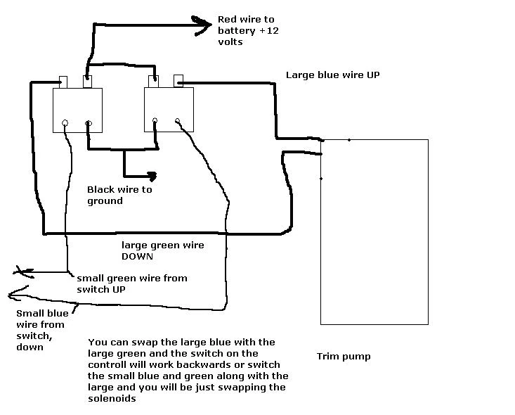
Variety of mercury trim motor wiring diagram. A wiring diagram is a simplified traditional photographic depiction of an electrical circuit. It shows the elements of the circuit as simplified forms, and the power and signal connections between the tools.
5. The word "Trim" and down and up arrows should be blinking. 6. Trim unit out to the maximum trim (not trailer) position. 7. Press the button to save. 8. Press the button to advance to 25.0 setting. ˇ ˚ Trim Sensor 25.0 Setting 9. The word "Trim" and up arrow should be blinking. 10. Use the trim switch and trim unit out to the ...
Mercury Trim Gauge Mercruiser Outboard Quicksilver 79 895292a01 Gauges Wiring Bottom Line Isle Of Man. I Have A Mercruiser 898r From 1983 The Trim Up Switch Stopped Working Couple Of Years Ago Trailer. Troubleshooting Drive Trims Down But Not Up Marine Engines And Sterndrives Fandom. Gauge Wiring Diagram For Mercruiser 383 New Install Boat ...
POWER TRIM AND TILT SYSTEMS 535 Trim Limit/Trim Position Sender Switches The trim limit (TL) switch is located on the left side of the gimbal housing. This switch permits only a limited amount of outward trim travel to provide safe control at high speeds and prevent damage to drive unit or trim cylinder due to lost side support of drive unit.
Electrical Wiring Mercury Outboard Trim Gauge Wiring Diagram How Tilt Trim Motor Tips Arco Viewing A Thread 2 Wire Motor Trim Wiring Diagram Troubleshooting Testing And Bypassing Spdt Power Trim Tilt Relays How To Install A Trim And Tilt On My1979 70hp Johnson Which ...











0 Response to "44 mercury trim gauge wiring diagram"
Post a Comment