44 draw a ray diagram representing your experiment from part c
Draw ray diagrams to represent the nature, position and relative size of the image formed by a convex lens for the object placed : ... (c) Draw a ray diagram to show the formation of image. Mark clearly F and 2F in the diagram. ... A student did an experiment with a convex lens. He put an object at different distances 25 cm, 30 cm, 40 cm, 60 cm ... Hence give a reason for the term 'burning glass' for a converging lens used in this manner. Medium. Open in App Open_in_app ...1 answer · Top answer: The sun is at infinity so convex lens forms its image at second focal point which is real and very much diminished in size.While using the convex ...
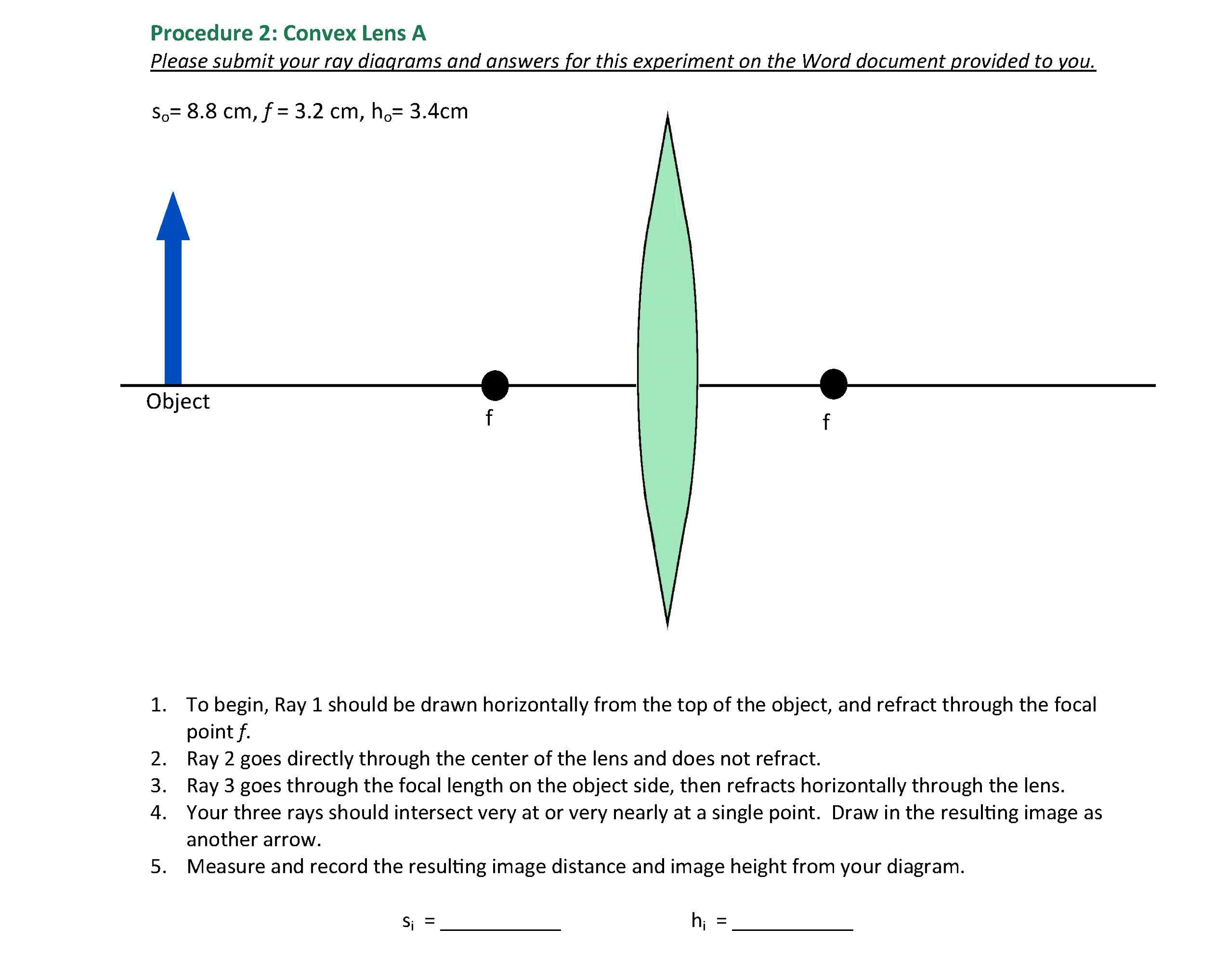
Draw a ray diagram representing your experiment from part c. Assume the object is in focus. On the diagram rays lines with arrows are drawn for the incident ray and the reflected ray. Representing refraction with ray diagrams it is useful to draw ray diagrams to understand how the geometrical optics concepts we have discussed previously. The method for drawing ray diagrams for concave mirror ...

Draw a ray diagram representing your experiment from part c
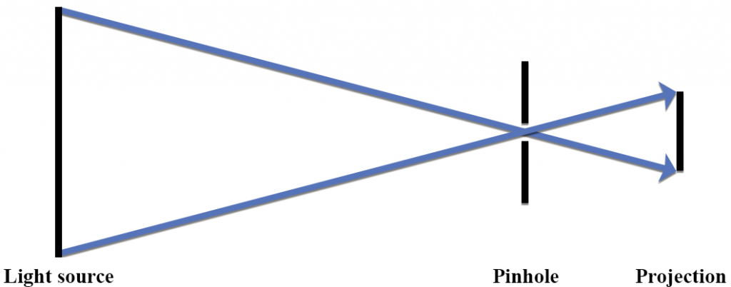
On your original diagram, add the light rays that would make it from the light source in its new position to the screen. How would the position of the light spot on the screen change? 3. Draw a new ray diagram for a similar situation with a new light source, in the shape of a vertical arrow that emits light from all parts. Step-by-Step Method for Drawing Ray Diagrams. The method of drawing ray diagrams for double convex lens is described below. The description is applied to the task of drawing a ray diagram for an object located beyond the 2F point of a double convex lens. 1. Pick a point on the top of the object and draw three incident rays traveling towards the ... These three rules will be used to construct ray diagrams. A ray diagram is a tool used to determine the location, size, orientation, and type of image formed by a lens. Ray diagrams for double convex lenses were drawn in a previous part of Lesson 5. In this lesson, we will see a similar method for constructing ray diagrams for double concave ...
Draw a ray diagram representing your experiment from part c. Part A . Plane Mirrors. Drawing a ray diagram is fairly simple for a plane mirror. Firstly we should draw an incoming ray: Figure 1: A diagram showing a ray incident on a plane mirror from an object. Notice that the object is clearly labelled and the direction of travel is indicated with an arrow on the ray. Once the incoming ray is drawn, a line perpendicular to the mirror, at the point where ... 17.2.2019 · b. draw a ray diagram showing the positions of both the images. OR. The plane surface of a planoconvex lens of focal length 60 cm is silvered. A point object is placed at a distance 20 cm from the lens. Find the position and nature of the final image formed. 27. Drawing concave mirror ray diagrams in optics with a real image part 1. Draw a ray diagram representing your experiment from part c. Draw a ray diagram representing your experiment from part c entitled as draw a ray diagram representing your experiment from part c software framework for controlling unsupervised scientific instruments also describes software framework for controlling ... A.) The sound waves were pushed closer together. Emmy is running a marathon to try to get a Boston time. She runs at a constant velocity of 6mph from 7:00 am to 9:00 am. At 10 a, her velocity was 8mph. She completed her race at 10:30am at a velocity of 10mph. Calculate her acceleration from 10:00am-10:30 am.
Lillian C. McDermott, Physics Education Group · 1995 · ScienceFor each of your eye locations in that experiment , draw a ray that shows the entire path of ... Nail C. Compare your ray diagrams for parts A and B above . The method for drawing ray diagrams for concave mirror is described below. The method is applied to the task of drawing a ray diagram for an object located beyond the center of curvature (C) of a concave mirror. Yet the same method works for drawing a ray diagram for any object location. 1. Pick a point on the top of the object and draw two ... Using a protractor, draw a normal at C, roughly the middle of AB. Draw a line at 20 o to the normal. Position a plane mirror carefully along AB. Direct a ray of light from a ray box along the 20 o ... Chapter 5 – Covalent Bonds and Introduction to Organic Molecules Chemical bonds are generally divided into two fundamentally different types: ionic and covalent. In reality, however, the bonds in most substances are neither purely ionic nor purely covalent, but lie on a spectrum between these extremes.
Have your academic paper written by a professional. Have your academic paper written by a professional +1(978) 822-0999. Course Help Online. Your number one essay writing service. ... You can have the privilege of paying part by part for … 5. Redraw Figure 9 for your lab report to practice ray tracing . 6. Is the image upright or inverted? Is the magnification greater or less than one? Describe the image. Also include the following in your lab report as part of Experiment 1: 7. Make a ray diagram for an object placed closer to a diverging (concave) lens than the focal point. 6.2.2010 · 3 March 2021: Observation of two c c u s tetraquarks and two c c s s tetraquarks. Welcome to tetraquark discovery territory Today, the LHCb Collaboration submitted a paper for publication that reports the first observation of two tetraquarks with a new quark content c c u s , decaying to the J/ψ and K + mesons: a narrow one, Z cs (4000) + , and a broader one Z cs … Draw the following diagram in your answer book and show the formation of image of the object AB with the help of suitable rays. (CBSE 2008) Answer: Question 2. Draw ray diagrams to represent the nature, position and relative size of the image formed by a convex lens for the object placed: (a) At 2F
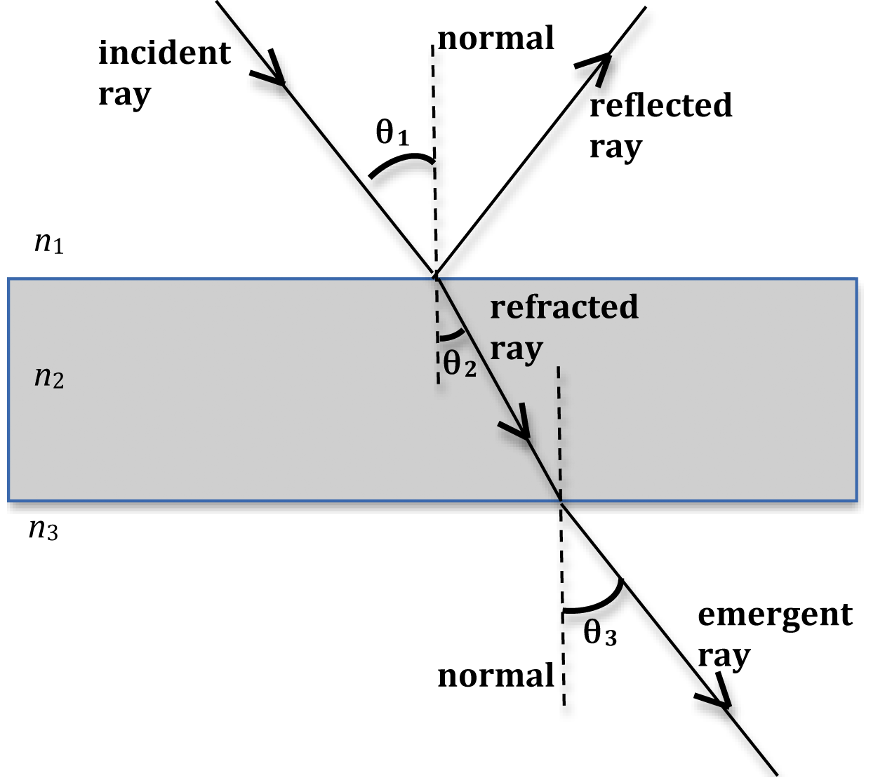
Q4) Draw a diagram showing the reflection of a light ray from a plane mirror. Label on it the incident ray, the reflected ray, the normal, the angle of ...1 answer · Top answer: Solution : AO is the angle of incident OB is the angle of reflection ON is the normal

The scientific method is an empirical method of acquiring knowledge that has characterized the development of science since at least the 17th century (with notable practitioners in previous centuries). It involves careful observation, applying rigorous skepticism about what is observed, given that cognitive assumptions can distort how one interprets the observation.

25 Jan 2017 — Draw A Ray Diagram Representing Your Experiment From Part C ... The method for drawing ray diagrams for concave mirror is described below.
correctly substituted into an otherwise correct solution to part (b), ... focal length and image size were represented in the ray diagram they drew.14 pages
Drawing Ray Diagrams - a Step-by-Step Approach. This section of Lesson 2 details and illustrates the procedure for drawing ray diagrams. Let's begin with the task of drawing a ray diagram to show how Suzie will be able to see the image of the green object arrow in the diagram below. For simplicity sake, we will suppose that Suzie is viewing the ...
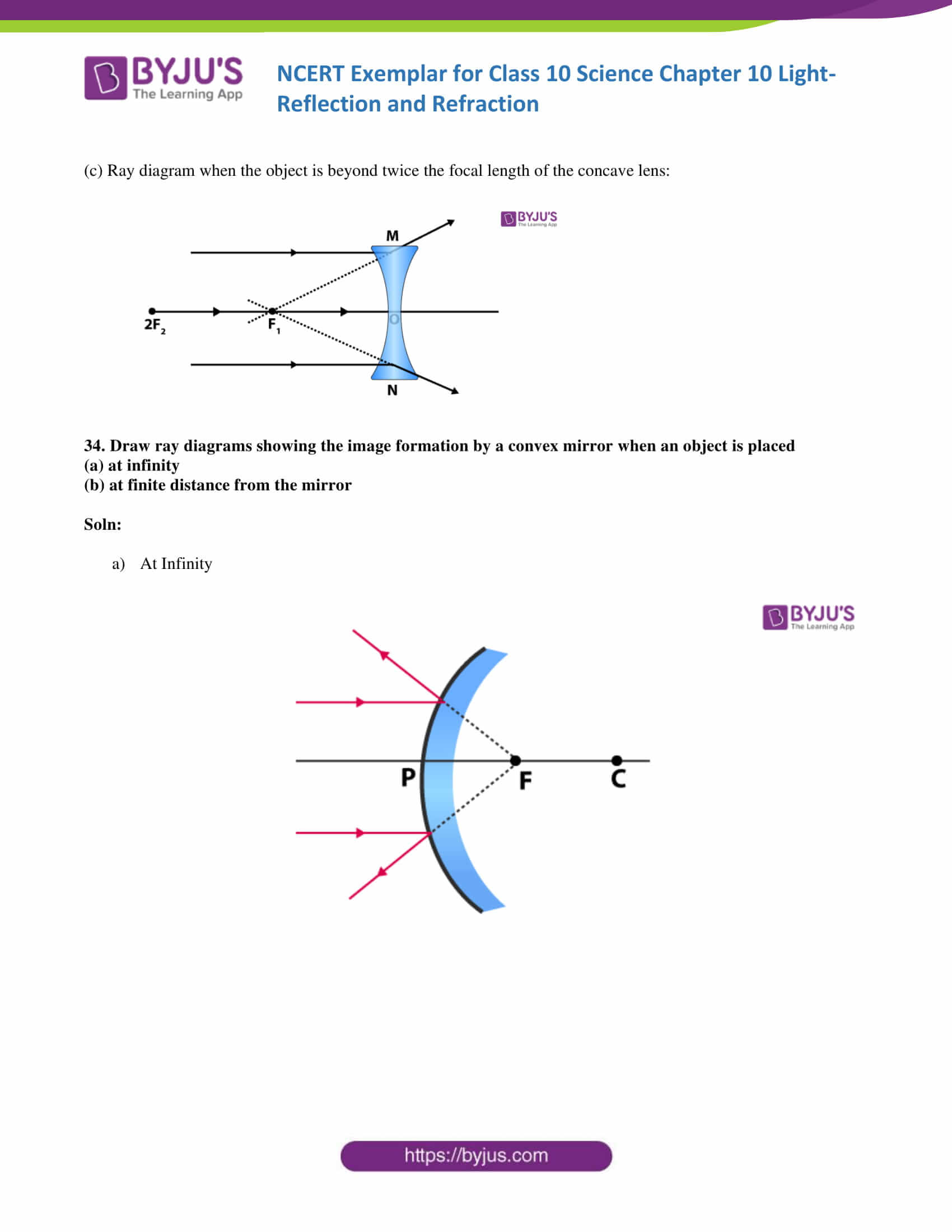
A ray diagram shows the path of light from an object to mirror to an eye. A ray diagram for a convex mirror shows that the image will be located at a position behind the convex mirror. Furthermore, the image will be upright, reduced in size (smaller than the object), and virtual. This is the type of information that we wish to obtain from a ray diagram.

A real image is an image that can be projected onto a screen. A virtual image appears to come from behind the lens. To draw a ray diagram: Draw a ray from the object to the lens that is parallel ...

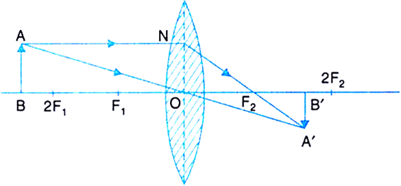
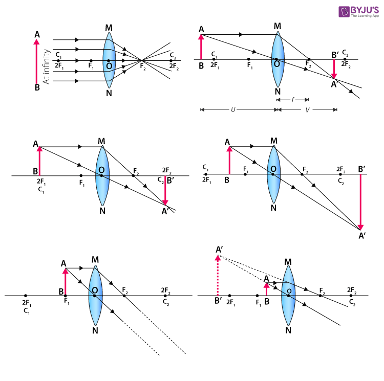
First, we draw a ray parallel to principal axis. So, it passes through focus after refraction. We draw another ray which passes through Optical Center. So, the ray will go through without any deviation. Where both rays meet is point A'. And the image formed is A'B'. This image is formed between F 2 and 2F 2. We can say that.
An incident ray that crosses C will result in a reflected ray that leaves the mirror crossing C. Figure 4: If an incident ray crosses C, its reflection will cross C. Examples of ray diagrams for ...

This is a short tutorial on how to draw ray diagrams for plane mirrors. Click on the images to view a larger version. Initially, we have an object in front of a plane mirror. First, we draw an image of the object on the other side of the mirror. Distance A is equal to distance B and the image size is the same size as the object size. Second, we draw light rays from the image to the eye. The ...
Draw a ray diagram representing your experiment from part c. In such cases it is customary to draw rays for the extreme positions of such objects. This section of lesson 2 details and. The method for drawing ray diagrams for concave mirror is described below. First draw a set of axis and draw the lens at the origin. See figure 2 5 now draw draw another light ray diagram for a human eye ...

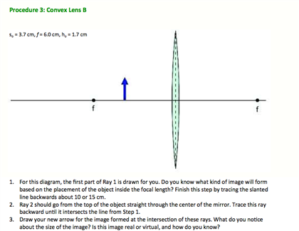
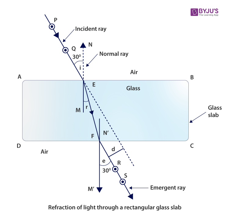
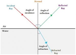
Draw a ray diagram representing your experiment from part c. Draw a line normal to the boundary. Show the ray bending in the correct direction. Representing refraction with ray diagrams it is useful to draw ray diagrams to understand how the geometrical optics concepts we have discussed previously. Ray 1 should be drawn horizontal from the top of the object and reflect through the focal point ...
Ing a free body diagram is part of the draw step in the analysis. Draw a ray diagram. Light Reflection And Refraction S Chand Dronstudy Com The system to be considered is a person and a. Draw a ray diagram representing your experiment from part c. Do not change this position during this part of the experiment. Ray 1 should be drawn horizontal from the top of the object and reflect through the ...

3. From this experiment, determine the positions where you can see the pin with your open eye. Draw light rays on the diagram below to support your hypothesis. Remember, the light rays come from the object and go to the eye. 4. Philosophy alert: If you observe the image of the object, and then close your eyes, does the image still exist? Explain.
Moa, C., Ozer, Z., Zhou, M. and Uckun, F. X-Ray Structure of Glycerol Kinase Complexed with an ATP Analog Implies a Novel Mechanism for the ATP-Dependent Gylcerol Phosphorylation by Glycerol Kinase. Biochemical and Biophysical Reaearch Communications. 1999, 259, 640-644.
This ray heads toward F, emerging parallel to the principal axis after reflection. Ray 2 is analogous to ray 1, except that the reflected, rather than the incident, ray is parallel to the principal axis. Ray 3. This ray travels toward the center of curvature C; as a result, the ray strikes the mirror perpendicularly and reflects back on itself.

10 Science - Free ebook download as PDF File (.pdf), Text File (.txt) or read book online for free.
Drag the labels onto the diagram to identify the classes of epithelia. Drag the labels onto the diagram to identify the classes of epithelia ...
Click here👆to get an answer to your question ️ (a) Draw ray diagram of refraction of light through a prism and explain the phenomenon of dispersion of light.(b) Write the formula for lens power and define its unit.
Ray diagrams help us trace the path of the light for the person to view a point on the image of an object. Ray diagram uses lines with arrows to represent the incident ray and the reflected ray. It also helps us trace the direction in which the light travels. Plane Mirror vs Spherical Mirrors

Development Economics by Debraj Ray. R. Ramisha. Download Download PDF. Full PDF Package Download Full PDF Package. This Paper. A short summary of this paper. 34 Full PDFs related to this paper. Read Paper. Development Economics by Debraj Ray.
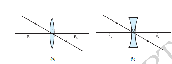
These three rules will be used to construct ray diagrams. A ray diagram is a tool used to determine the location, size, orientation, and type of image formed by a lens. Ray diagrams for double convex lenses were drawn in a previous part of Lesson 5. In this lesson, we will see a similar method for constructing ray diagrams for double concave ...

Step-by-Step Method for Drawing Ray Diagrams. The method of drawing ray diagrams for double convex lens is described below. The description is applied to the task of drawing a ray diagram for an object located beyond the 2F point of a double convex lens. 1. Pick a point on the top of the object and draw three incident rays traveling towards the ...

On your original diagram, add the light rays that would make it from the light source in its new position to the screen. How would the position of the light spot on the screen change? 3. Draw a new ray diagram for a similar situation with a new light source, in the shape of a vertical arrow that emits light from all parts.


0 Response to "44 draw a ray diagram representing your experiment from part c"
Post a Comment