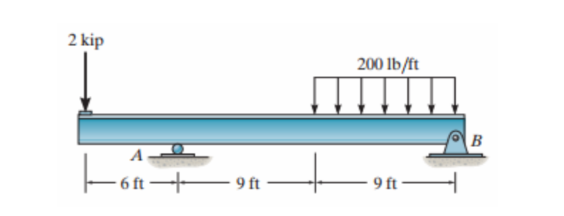
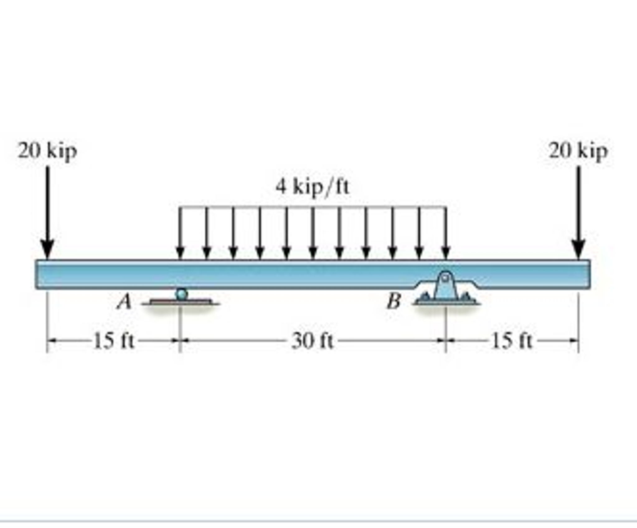
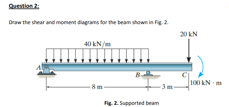
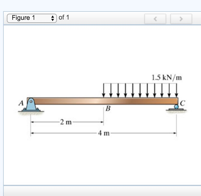
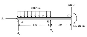
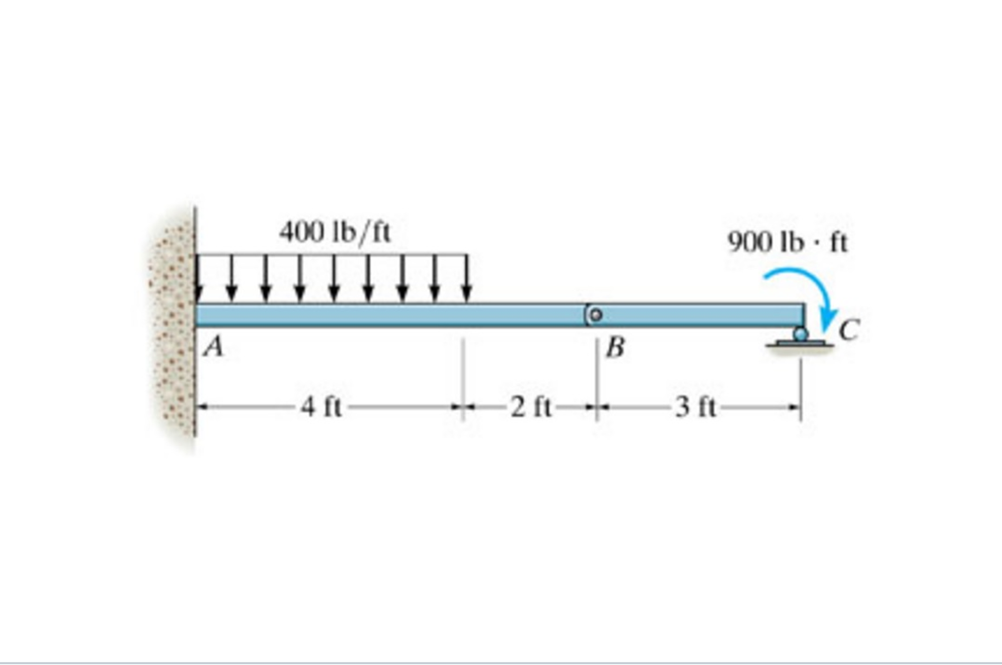
42 draw the shear diagram for the beam.
Draw the shear and moment diagrams for the beam. Draw shear force and bending moment diagram of simply supported beam carrying uniform distributed load and point loads.
Our approach to drawing the shear force diagram is actually very straightforward. We're going to 'trace the impact of the loads' across the This process of following or tracing the loads across the structure continues across the full beam until you've completely traced out the shear force diagram.
Free online beam calculator for generating the reactions calculating the deflection of a steel or wood beam drawing the shear and moment di...
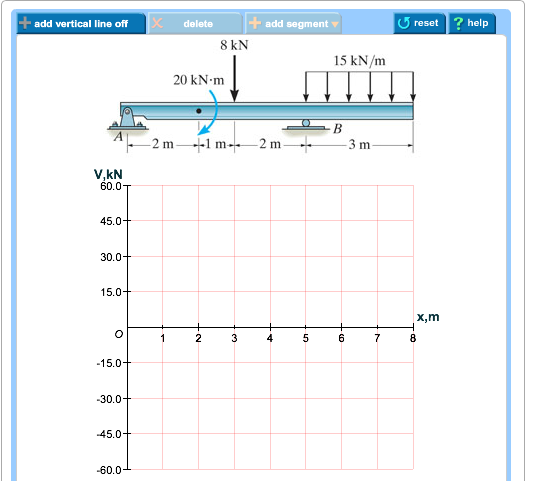
Draw the shear diagram for the beam.
Shear design of reinforced concrete (RC) beam involves the determination of spacing between stirrups. Compute shear force on the beam by using equation or draw shear diagram We will determine these locations and superimposed on the shear diagram of the beam.
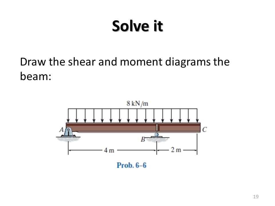
3 Shear and moment diagram Axial load diagram Torque diagram Both of these diagrams show the internal forces acting on the members. 13 Boundary cond for V and M M=5x M=10-5x. 14 Solve it Draw the shear and moment diagrams for simply supported beam.
A simply supported beam that has a pen doing here in a room where enjoying here, roller here way have the distributed load is linearly bearing, but it And the moment arm for this one is 2/3. That's that means we can figure out what the sheer and the bending moment are by looking at by looking at free...
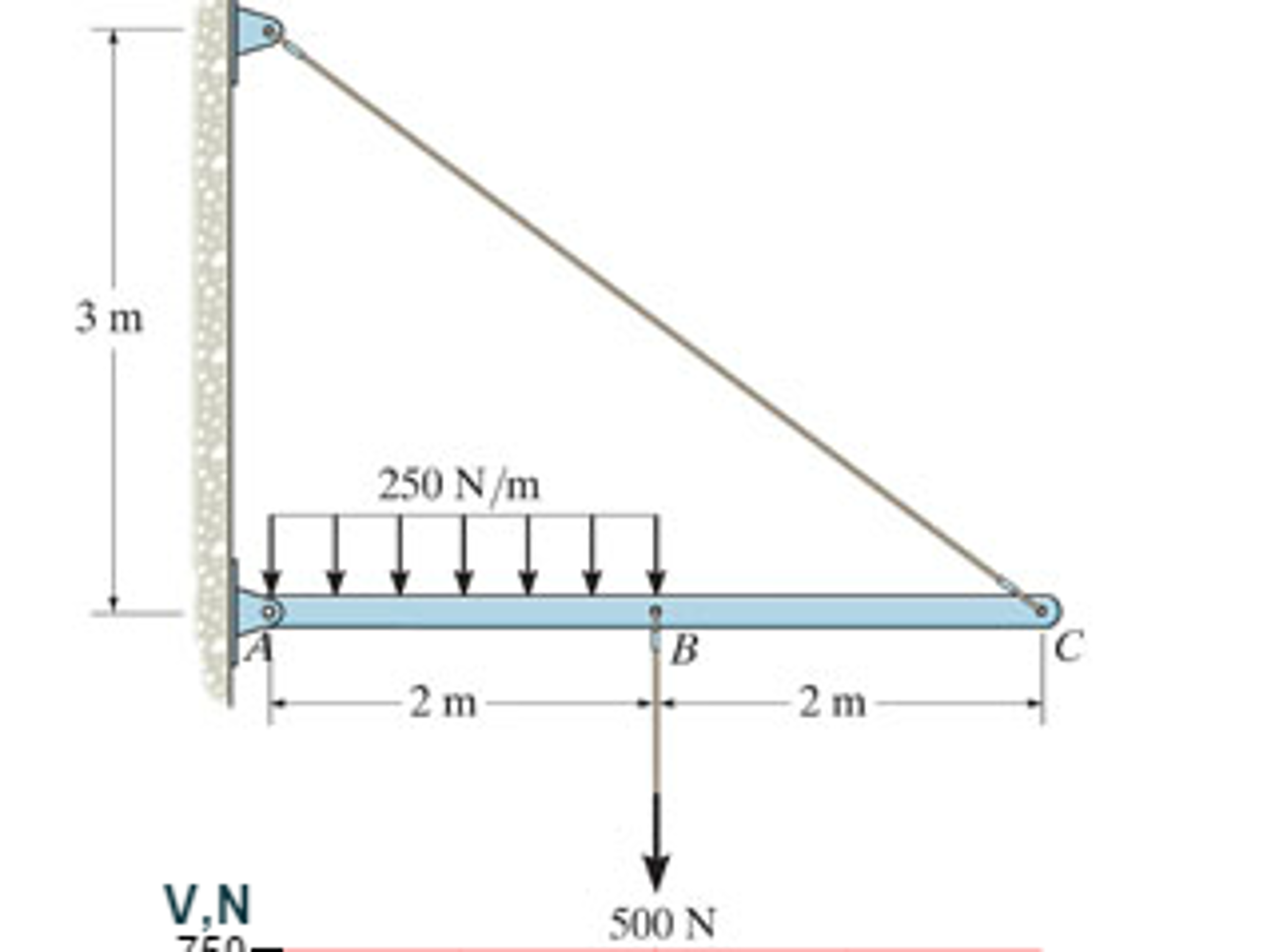
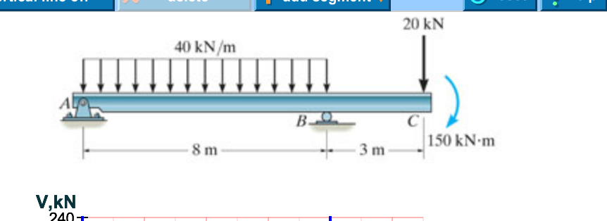
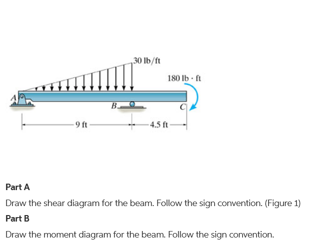
Draw the shear diagram for the beam..
Draw the shear and moment diagrams for cantilever beam chegg. Assume the supports at a is fix c is roller and b is pin connections. Correct problem 753 part a draw the shear diagram for the beam. Note 1 you should not draw an extra discontinuity line at the point where the curve passes the x axis.
Click on add vertical line off to add discontinuity lines. The first step obtaining the bending moment and shear force equations is to dete...
Hi guys, I'm loosing sleep over this question, we haven't been specifically taught this but maybe it's obvious and I'm just missing it completely but can someone please explain a method to this? Question: An overhead crane has a trolley and hoist weighing 300kg. The designation of the supporting I beam is 457x191x89 and the bridge is 10m long. The bridge is designed to have a factor of safety of 3. The beam is manufactured from steel having yield strength of 440MN/m^2 The runway beams at the e...
To calculate the shear forces of a beam follow the following simple steps. If there is an upward force ie a support then the sfd will start...
Let me preface this by saying why I went into engineering, and why specifically ME. My neighbors were basically a huge influence on me. They got me into engineering by showing me around their work places(telecommunications and refining). I ended up getting real interested in the engineering career field. They helped me get into engineering. Then in high school I took a course that had us deal with projects like building and designing windmills, wind turbines(small scale), looking at refining ...
Button to add functions between the lines. Follow the sign convention. How To Draw Shear Force And Bending Moment...
Hey guys I am struggling with a Mohrs Circle question and would love some help. I'm not sure if answering questions is the purpose of /r/engineering, so if not feel free to not reply. Anyway, the question is as followed: I have one 2m length I beam with a 120kN/m load. The point under consideration is P which is 0.3 metres in from the left side. I am given the compressive bending stress and longitudinal shear stress. From this I am supposed to draw a stress block diagram and then Mohrs Circle...
Then you can proceed to next step. In particular, they identify the . In the case of the beam shown , these 3 are the reaction...
The problem that I am working on is looking at a 2.4ft beam that is in equilibrium with the loads as [shown](http://imgur.com/Bw3dWfD). I am to find the maximum normal stress due to bending. Tell us what is holding you up. Oh what is holding me up, I have been having trouble with these as it has been two years since statics, and it is tough to refresh my memory. Currently I have found the concentrated force to be **(1/2)*50(lb/ft)*1.2ft = 30lb** and i know that this force if you are mov...
Draw The Shear Diagram For The Beam . A beam is in equilibrium when it is stationary relative to an inertial reference frame. It is visuall...
Hey everyone, I need some help with a question I have, I think I've done parts a and b correct, but I'm struggling with part c. The breaking the beam up into sections is hard for me and the bending moment is hard for me to wrap my head around. Here's the question: Beam EAB is 7.5m long and is simply supported at A and B. Support at A is a roller support and at B is a pin support. EA is overhang of 2m. It carries point loads as shown: a) Calculate the support reactions b) Determine the shea...
This is the end of the preview. Sign up to view the full version. Seismic Performance Parameters For Reinforced Concrete Bl...
Im having trouble tackling this problem Draw the shear and bending-moment diagrams for the beam and loading shown, and determine the maximum absolute value (a) of the shear, (b) of the bending moment. http://i.imgur.com/WxiH8.jpg the first thing i did was mb=0 (-4kn*1m) -4kn*2m+fa(2.5m) fa = 4.8 fb = 3.2 am i on the right track? is there a better subreddit for this? I could not find one
The distributed load applies a load at every single point that it covers so infinitely many shear decreases over any horizontal distance.
Can someone please take me through the whole process of working out and drawing these diagrams? Here is an example: http://i.imgur.com/5FZBcLx.jpg?1 Q: Draw shear force and bending moment diagrams for the following beams. Label the diagrams with important values.
Draw the shear and moment diagrams for the beam. First find reactions r1 and r2 of simply supported beam. Mechanics e shear moment diagrams draw the shear and moment diagrams for beam determine in as functions of x where 4 ft 10 study ering mechanics statics pages 351 400 flip fliphtml5...
I've been having some difficulty solving this problem (7.54), and I just can't figure out how to solve it. [Ignore everything that its written in pencil :P](http://i.imgur.com/bjb93.jpg) The answer is a=1.063m and Mmax=8.50kN I figured that Mmax = 8*a and the closest I've been to the answer is by calculating the shear force and bending moment at the middle of the beam, eg (0.875 +a/2)m. However it isn't exactly the right answer. Thanks for the help :) EDIT: The hint of prob 7.51: "Draw the ben...
Draw the shear and moment diagram for the beam on diagram link. This beam calculator is designed to help you calculate and plot the bending moment diagram bmd shear force diagram sfd axial force diagram.
Study Guide for EM 319 Midterm #2 (Note: the order of the following listed items does not matter.) 1. Be able to perform FBD and EQM of torsion problems. 2. Be able to describe, draw, and calculate internal torque and shear stress in torsional members. 3. Be able to describe, draw, and calculate angle of twist and shear strain in torsional members. 4. Be able to describe the torque-twist relation. 5. Be able to describe the shear stress - shear strain relation. 6. Be able to differentiate the an...
How to draw shear diagrams. In this tutorial we will look at calculating the shear force diagram of a simple beam. Draw Mom...
How do I draw a bending moment and a shear force diagram for a beam with a UDl across it's entire length, with unequal Pin Point loads at equal points along the beam? Many thanks!
You are watching: Draw the shear diagram for the beam. This way that in ~ the point of application of a bending moment, over there is a step change in the bending moment diagram, equal to the magnitude of the minute applied. The 6 boxed equations in this section above can be used to infer a...
Why don't we break up moments into forces? I'm making up this problem for example. Let's say you have a beam 10m long. There's a concentrated clockwise moment of 4N*m at 4m. It's got a pin connection at 0m and a roller at 10m. What the difference between a 4N*m moment at 4m and a 1N force at 0m? Or a 2N force at 2m? Also, what's the significance of shear and moment diagrams? What information does a shear moment diagram give about the beam? Same question goes with a moment diagram. I know ...
Then click on "add segment" button to add functions between the lines. [image] Part B Draw the bending-moment diag… Draw the bending-moment diagram for the beam.
A little over a month ago I started to educate myself a little in civil engineering since I have worked as a drafter for two years in a construction company. I'm just learning basic statics at the moment and came across this beam in the picture - http://i.imgur.com/SHpBLaO.jpg. I found the reactions to be (starting from left) - 8,73 kN, 9,07 kN, 34,83 kN and the last one 0,57 kN. Actually I'm not even sure they are correct. The sum of all forces in the vertical direction turned out zero. But ...
The simple supported beam is a beam which has one end hinged and the other roller supported. Hinged support will have two reactions (vertical and To draw the shear force diagram we take the distances on x-axis and the shear force values on y-axis and join the points. Wherever there is point...
When drawing shear and moment diagrams using the method of sections, how does changing the origin affect the graph drawn. For example, if for the first two sections I used point A which is at the left most point of the beam then used another point to measure my moment from, how should my strategy of drawing my graph change? Thanks
Draw the shear and moment diagram for the beam shown in figure. The resulting graphics are called the shear diagram and moment diagram. Since the same x was used for all three sections, the each equation for each section can be easily plotted as shown at the left.
Hey guys, I'm a late-twenties ME who's reteaching myself my undergrad curriculum for the sake of technical interviews (ugh). Thanks bay area. Anyway, I'm rolling through my statics and I'm having a little problem with shear and moment diagrams. The concept is straight forward. I've no problem calculating the reaction forces. But when I'm drawing my shear diagram, cutting my beam from left to right, I struggle to figure out which direction to draw my shear. My 1960's statics textbook is good bu...
Write shear and moment equations for the beams in the following problems. In each problem, let x be the distance measured from left end of the beam. Also, draw shear and moment diagrams, specifying values at all change of loading positions and at points of zero shear.
Transcribed image text: Part A Draw the shear diagram for the beam. Begin by placing the lines of discontinuity.
Hey!I am trying to understand what all the different equations for a free beam mean.In the picture you can see the free beam and it's formulas.I dont understand how w(x) (x=a) is different than w(x) (x<=a).I think it might boil down to me not fully understanding the difference between a and x. The problem i am working is below. "Draw shear and moment diagram for the beam" https://preview.redd.it/8n2d62hjnm241.jpg?width=831&format=pjpg&auto=webp&s=36efd78232676e99dc36ef21a3a89447...
Draw the shear and bending-moment diagrams for the beam and loading shown, and determine the maximum absolute value (a) of the shear, B (b) of the bending moment. 300 mm.
Looking at a beam problem; multiple point loads and **fixed at both ends...**a problem that seems to be the forbidden analysis bc I cannot find any example or forum post on it - I know it’s statically indeterminate but I figured it was still doable. I was able to easily figure out the reaction forces and moments, construct the shear & moment diagrams...I cannot however figure out to do the deflection. There is an [online calc](https://amesweb.info/Beam/fixed-beam-deflection-calculator.aspx) ...
to draw the bending moment diagram we will determine the areas of A1 and A2 on the shear force diagram . Strength of materials deals with this drawing of shear force and bending moment diagram for statically determinate beam , where as the methods of drawing SF and BM diagrams...
It was just another normal walk. That’s how it started anyway; a casual morning stroll on the forested trail that ran behind my parent’s house. They own a home on a couple acres in the small town of Skyline, Alabama. At the time I was in between jobs, and had been living with them as I tried to get back on my feet. Their property intersects with a winding trail that ran for miles through some unkempt woods in the boonies. In the morning, the Appalachian hills would come alive with the songs of...
4.3 Shear- Moment Equations and Shear-Moment Diagrams. ‰ The determination of the internal force system acting at a given section of a beam : draw a ƒ Plot the expressions for V and M for the segment. It is visually desirable to draw the V-diagram below the FBD of the entire beam, and then...
So, I'm studying for a test, and I can't find anywhere how to draw and calculate shear and moment diagrams for a Gerber beam, all the tutorials only show the single rigid beam example. So if anyone has any examples or explanations, I'd be very thankful. Cheers!
What software is suitable for drawing beams and shear & moment diagrams? Do you think AutoCAD is suitable? Or is there better ways? I can calculate them elsewhere, but I need the most easiest way to draw everything digitally.
...Shear Force Diagrams (SFD) and Bending Moment Diagrams (BMD) of a cantilever beam or simply supported beam. Use this beam span calculator to determine the reactions at the supports, draw the shear and moment diagram for the beam and calculate the deflection of a steel or wood beam.
*I thought I'd bring a little life into this subreddit by sharing stories from elsewhere on the web. Here's a helpful post I saw on the ARE 5.0 Community. I've put my summary up top, and then the original post down below with a link. If you guys like this, I'll share some more of these: I've got a whole collection.* ## Summary This is a report from Esther Campbell from the ARE 5.0 Community. First, she warns that the exams seem to vary drastically from person to person, so she’s not sure how...
Structural analysis of statically determinate beams. Define and calculate Shear Force in a beam, draw and calculate Bending Moment in a beam. Example 1. Simply supported beam calculation. Calculate the support reactions. Draw the Bending Moment diagram.
Hi fellow engineers. We use SAFI PSE at our office, it's a good program but it seems like it's not very widely used, and as such, it's hard to find plain-english answers for specific things online. It's a "ball and stick" structural analysis program where you can draw out your structure, assign constraints to joints, apply loads, etc. and view the results. Lots of good stuff. For the purposes of this discussion I'm going to assume none of you uses SAFI and probably won't be able to give me a...
This is an example problem that will show you how to graphically draw a shear and moment diagram for a beam. In general the process goes like this:1)...













0 Response to "42 draw the shear diagram for the beam."
Post a Comment