42 consider the circuit diagram depicted in the figure.
Voltage divider circuit with or without load. Consider the circuit shown below on the left side. It is easy to see that i = v. g. R. 1 +R. 2. and v. out ... It is easy to solve the above circuit. The solution is depicted in the first figure on ... from the simple circuit of Figure 4 to the circuit of Figure 3, and so on. ...
Consider this diagram. Let us assume that it describes a series circuit containing a resistor, a capacitor, and an inductor. The current in the circuit has amplitude , as indicated in the figure. Which of the following choices gives the correct respective labels of the voltages across the resistor, the capacitor, and the inductor?
Problem 1: Consider the circuit depicted in the attached figure. The voltage source is an AC source of frequency f = 55 Hz. R, Randomized Variables C, R1 = 103 Q R2 = 162 Q C1 = 6.5 µF C2 = 9.5 µF V C2 R2 L = 0.77 H Part (a) Given the above circuit, write an expression for the total impedance Z for the circuit as a complex number.
Consider the circuit diagram depicted in the figure.
Figure P 5.42 0.2 H *P5.42. Find the phasors for the current and for the voltages of the circuit shown in Figure P5.42. Construct a phasor diagram showing Vs, I, v R. and VL. What is the phase relationship between Vs and I?
Figure 6.13. State-assigned table for the sequential circuit in Figure 6.12. Present Next state state Outputs A 00 00 0 1 0 0 0 0 0 0 0 B 01 10 1 0 0 0 1 0 0 1 0 C 10 11 1 1 1 0 0 1 0 0 0 D 11 00 0 0 0 1 0 0 1 0 1
Consider the circuit shown in Figure (a). i L(0-) = 0, and v R(0-) = 0. But, -v R(0-) + v C(0-) + 10 = 0, or v C(0-) = -10V. (a) At t = 0+, since the inductor current and capacitor voltage cannot change abruptly, the ...
Consider the circuit diagram depicted in the figure..
Consider the circuit diagram depicted in the figure. 0 ω r 3 16. For the action depicted in the figure figure 2 indicate the direction of the induced current in the loop clockwise counterclockwise or zero when seen from the right of the loop. Now consider a diagram describing a parallel ac circuit containing a resistor a capacitor and an inductor.
For the action depicted in the figure, (Figure 2) indicate the direction of the induced current in the loop (clockwise, counterclockwise or zero, when seen from the right of the loop). The face of the south pole will become the north pole, so there will be a force of attraction between them, which makes the motion of the coil opposed.
Figure 12.2.2 (a) Time dependence of IR (t) and VR (t) across the resistor. (b) Phasor diagram for the resistive circuit. The behavior of IR (t)and can also be represented with a phasor diagram, as shown in Figure 12.2.2(b). A phasor is a rotating vector having the following properties: VR (t) (i) length: the length corresponds to the amplitude.
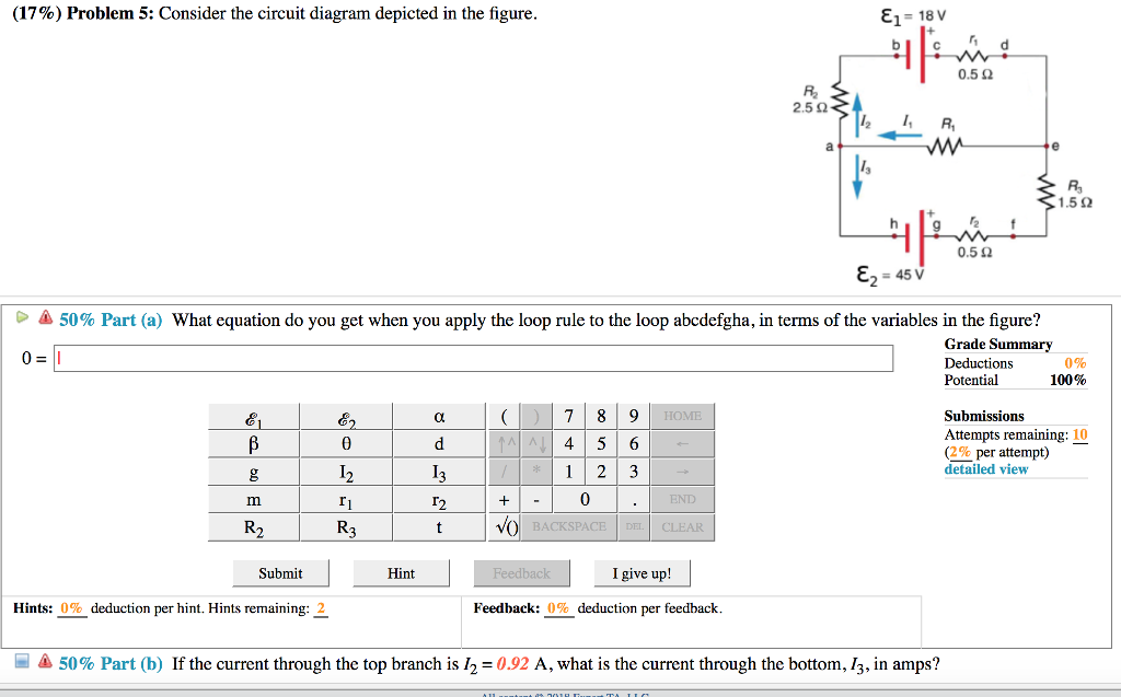
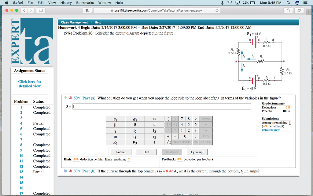
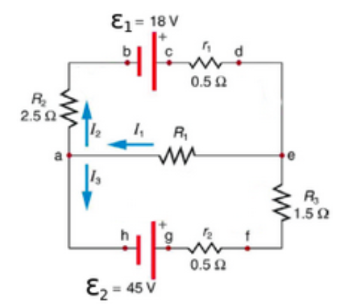
View (3) Problem 30 Consider the circuit diagram in the figure. E1 = 18V.docx from AA 1 (3%) Problem 30: Consider the circuit diagram in the figure. E1 = 18V R Ez = 45 Otheexpertta.c 50% Part (a)
Suppose that these systems are connected in series as depicted in Figure P3.10. Find the input-output relation for the overall interconnected system. Is this sys tem linear? Is it time-invariant? x[n] System 1 - System 2 System 3 y[n] Figure P3.10 (d) Consider a second series interconnection of the form of Figure P3.10 where the
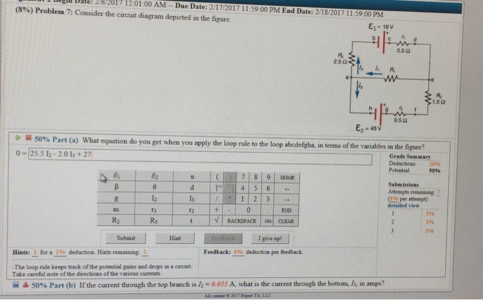
Consider the circuit diagram depicted in the figure. a. What equation do you get when you apply the loop rule to the abcdefgha, in terms of the variables in the figure?
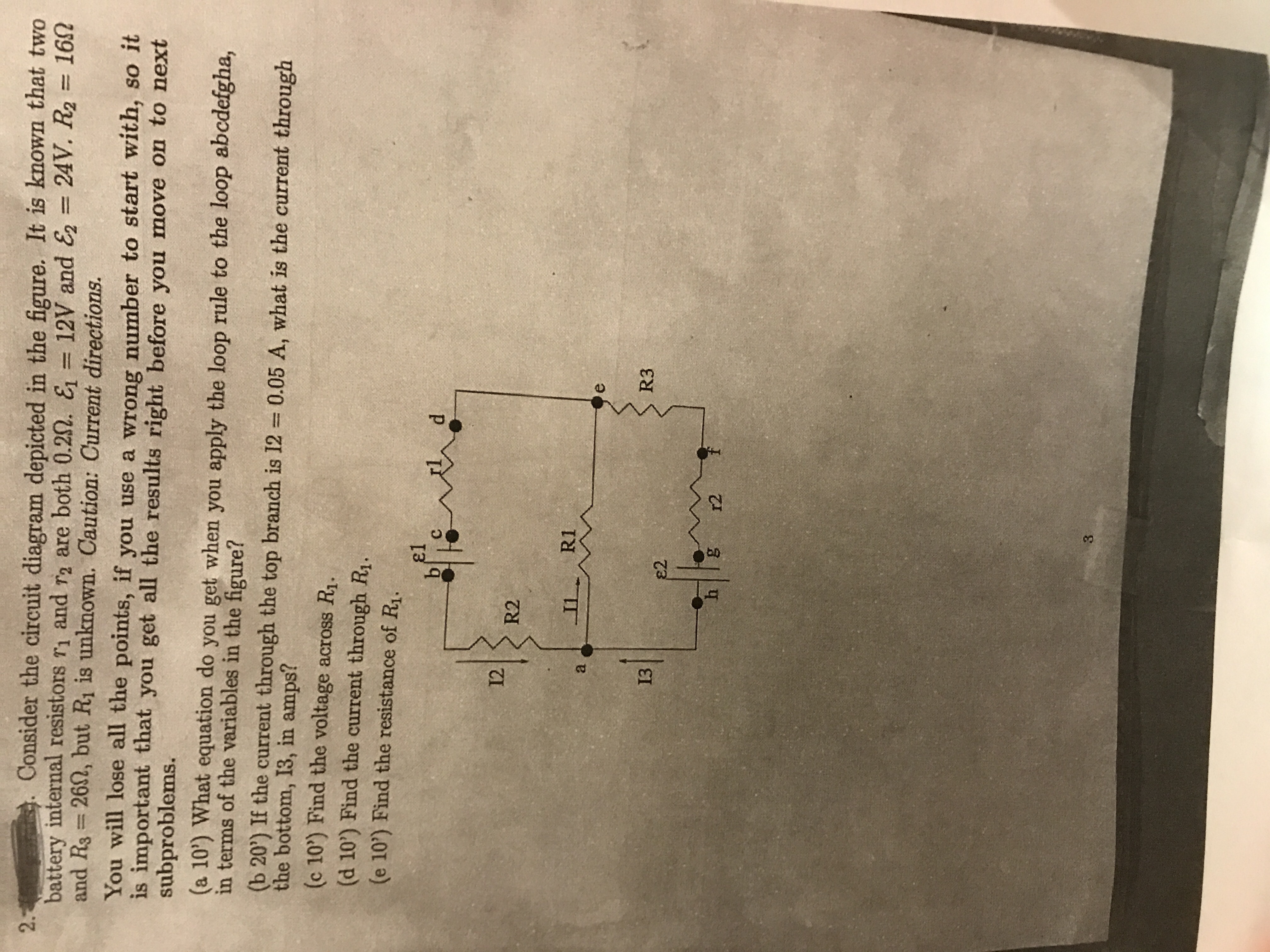
2. 27.3.2 (7, ex) Consider the circuit diagram depicted in the figure. (a) What equation do you get when you apply the loop rule to the loop abcdefgha, in terms of the variables in the figure? (b) If the current through the top branch is I2 = 0.085 A, what is the current through the bottom, I3, in amps? (c) Find the current through R 1 and the resistance of R 1.
Answer to: For the circuit shown in the figure, V1 = 14.6 V and V2 = 9.4 V. Determine the current in the 4.0 ohm resistor. By signing up, you'll...
P 5.2-2 Consider the circuit of Figure P 5.2-2. Find i a by simplifying the circuit (using source transformations) to a single-loop circuit so that you need to write only one KVL equation to find i a. Figure P 5.2-2 . Solution: Finally, apply KVL: 16 10 3 4 0 2.19 A aa 3 a
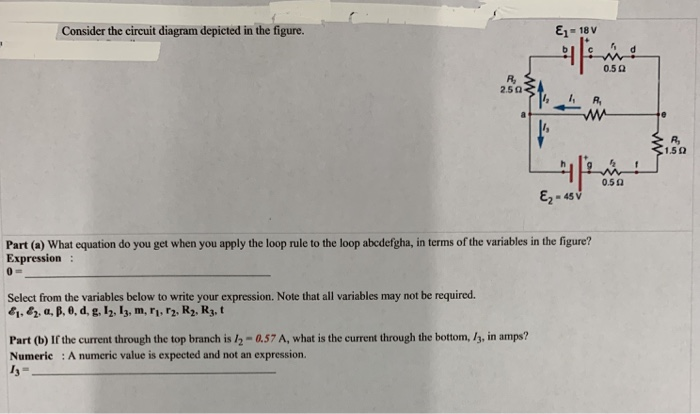
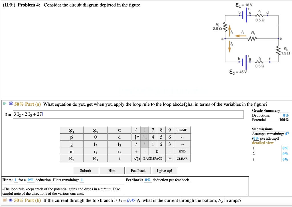
Transcribed image text: Consider the circuit diagram depicted in the figure. What equation do you get when you apply the loop rule to the loop abcdefgha, in terms of the variables in the figure? If the current through the top branch is I_2 = 0.47 A, what is the current through the bottom.
A) Consider the combination of capacitors shown in the diagram, where C 1 = 3.00 μF, C 2 = 11.0 μF, C 3 = 3.00 μF, and C 4 = 5.00 μF.. Find the equivalent capacitance C A of the network of capacitors. Express your answer in microfarads. B) Two capacitors of capacitance C 5 = 6.00 μF and C 6 = 3.00 μF are added to the network, as shown in the diagram. Find the equivalent capacitance C B ...
Answer to Solved (10%) Problem 10: Consider the circuit diagram. Transcribed image text: (10%) Problem 10: Consider the circuit diagram depicted in the figure. E1 = 18 V 250 R 0.522 E2-45V 50% Part (a) What equation do you get when you apply the loop rule to the loop abcdefgha, in terms of the variables in the figure?
Solved consider the circuit depicted in the diagram. | chegg.com
91% (345 ratings) Problem Details. Consider the circuit diagram depicted in the figure. Part (a) What equation do you get when you apply the loop rule to the loop abcdefgha? Part (b) If the current through the top branch is I2 = 0.49 A, what is the current through the bottom I3, in amps? Frequently Asked Questions.
Answered: consider the circuit diagram depicted… | bartleby
In this problem, we will consider the following situation as depicted in the diagram: A block of mass m slides at a speed v along a horizontal smooth table. It next slides down a smooth ramp, descending a height h, and then slides along a horizontal rough floor, stopping eventually. Assume that the block slides slowly enough so that it

Pdf) a new filter concept for high pulse-frequency 3-phase afe ...
Transcribed image text: (10%) Problem 5: Consider the circuit diagram depicted in the figure 0.5 Ω R2 2.5 Ω /2 R 1.5Ω 0.5 Ω 50% Part (a) what equation do you get when you apply the loop rule to the loop abcdergha, in terms of the variables in the figure? Grade= 100% Correct Answer Student Final Submission Feedback Correct! 012 R2+ 112 T3 R3 +32-62 0- 1-(Ti +R2) I2+(R3r2)13 2 Grade Summary ...
Passive and active topologies investigation for led driver ...
Consider the circuit diagram depicted in the figure. What equation do you get when you apply the loop rule to the loop abcdefgha? If the current through the top branch is I_2 = 0.49 A. what is the current through the bottom, I_3, in amps?

Topolectrical weyl circuit. a circuit diagram of the weyl ...
Consider the circuit shown in the figure below where c1 400 µf c2 700 µf and δv 180 v. 180 v v r 4 400 r 1 200 r 2 300 3 100 label the voltage v 180 v and the resistors. Calculate the power delivered to each resistor in the circuit shown in figure p2131. Consider the following circuit diagram.
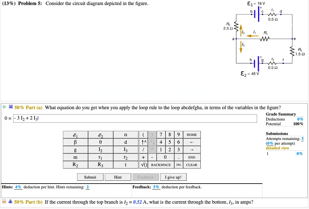
Solved:(13% ) problem 5: consider the circuit diagram depicted in ...
Question. Consider the circuit diagram depicted in the figure. What equation do you get when you apply the loop rule to the loop abcdefgha, in terms of the variables in the figure? 0 = If the current through the top branch is I_2 = 0.69 A, what is the current through the bottom, I_3, in amps?
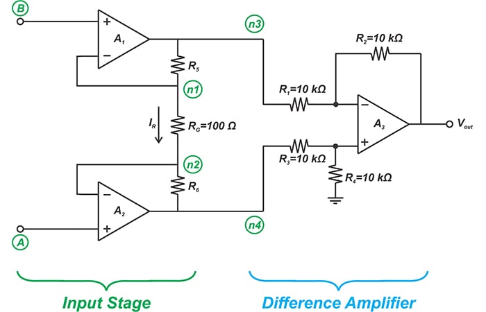
Learn about three-op amp instrumentation amplifiers - technical ...
Consider a series RC circuit as in the figure below for which R = 1.00 MΩ, C = 5.00 µF, and ε = 30.0 V. Find (a) the time constant of the circuit and (b) the...
Solved (17%) problem 5: consider the circuit diagram | chegg.com
They depict every component in a circuit, the component's technical information (such as its ratings), and how each component is wired into the circuit. Block diagrams are the simplest type of drawing.
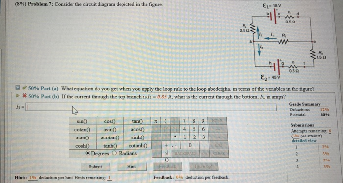
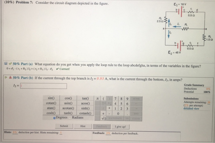
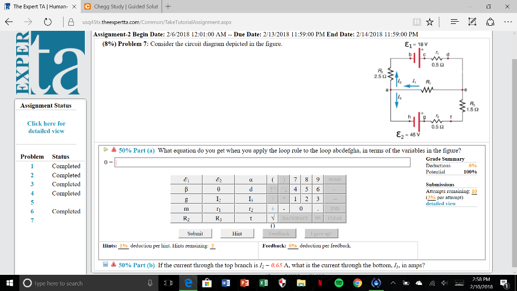
Solved (8%) problem 7: consider the circuit diagram depicted ...
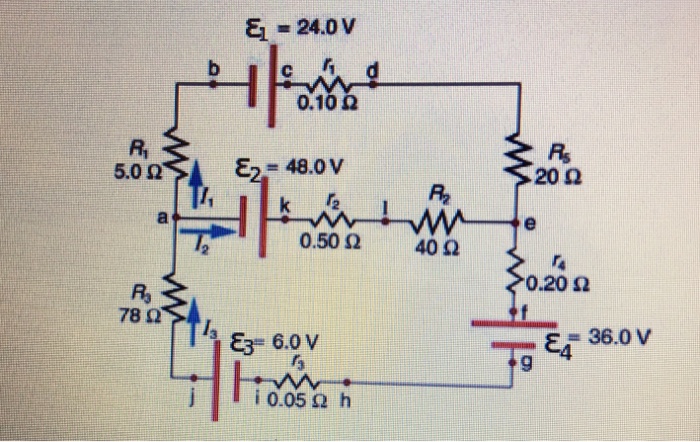
Consider the circuit diagram depicted in the fgure. It is known that two battery internal resistors r1and r2 are both 0.2Ω· = 12V and & = 24V. R2 16Ω 2. and Rs 262, but Ri is unknown. Caution: Current directions.
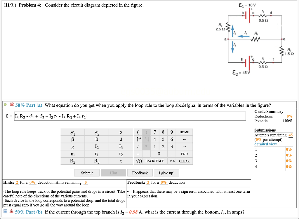
Solved (11%) problem 4: consider the circuit diagram | chegg.com
Sample Circuit We consider the ... Consider the circuit shown in Figure P28.9. Find (a) the current in the 20.0-Ω resistor and (b) the ... Draw the circuit diagram and assign labels and symbols to all known and unknown quantities. Assign directions to the currents.
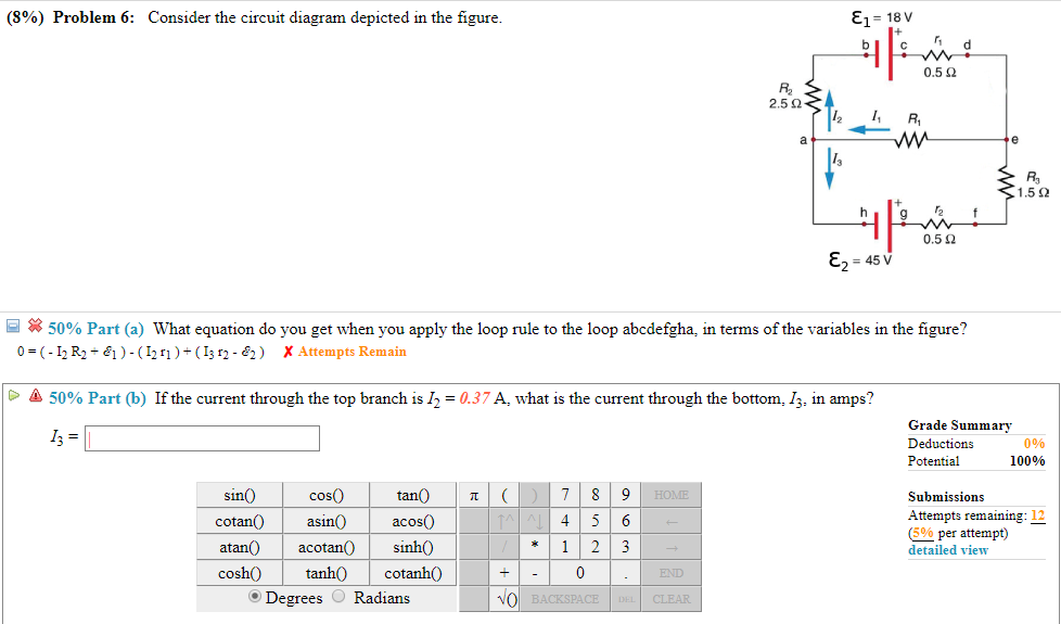
Solved (8%) problem 6: consider the circuit diagram depicted ...
Figure 12.2.2 (a) Time dependence of IR (t) and VR (t) across the resistor. (b) Phasor diagram for the resistive circuit. The behavior of IR (t)and can also be represented with a phasor diagram, as shown in Figure 12.2.2(b). A phasor is a rotating vector having the following properties: VR (t) (i) length: the length corresponds to the amplitude.
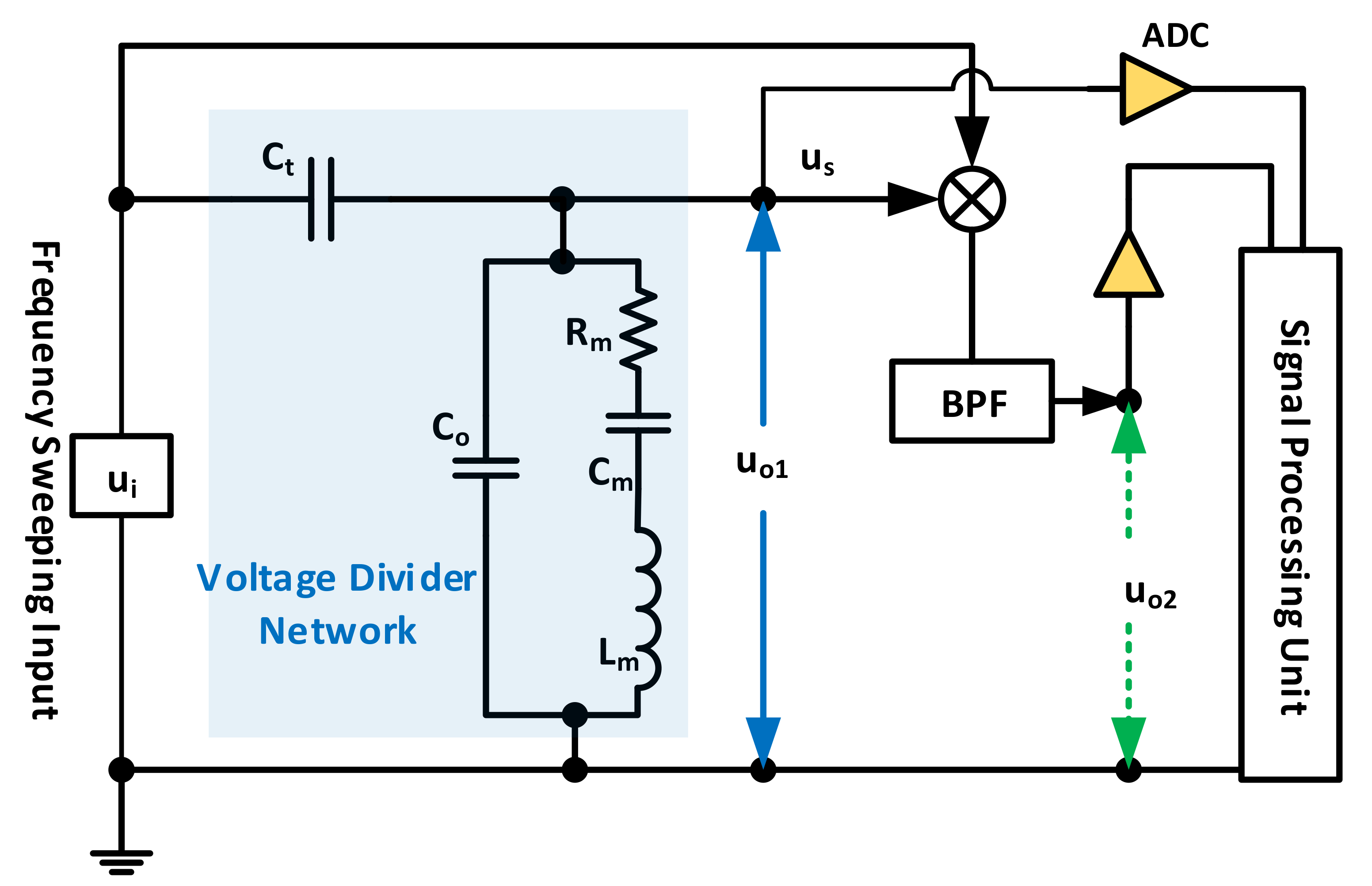
Sensors | free full-text | quartz crystal microbalance electronic ...
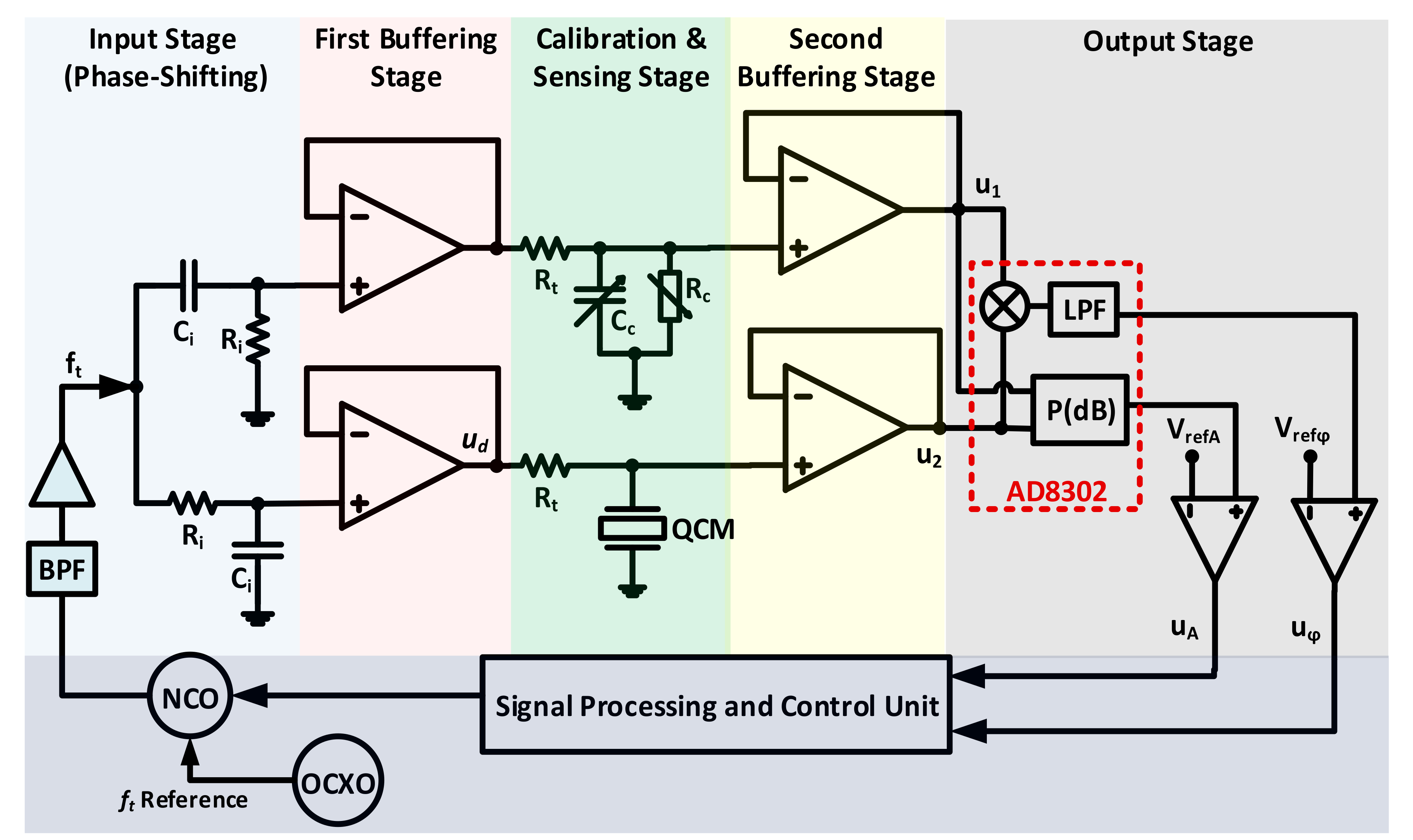
Sensors | free full-text | quartz crystal microbalance electronic ...
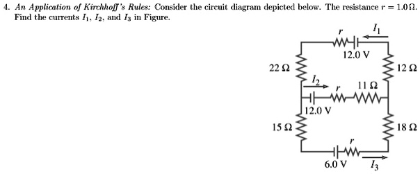
An application of kirrchhoff ` rules: consider the cir… - itprospt
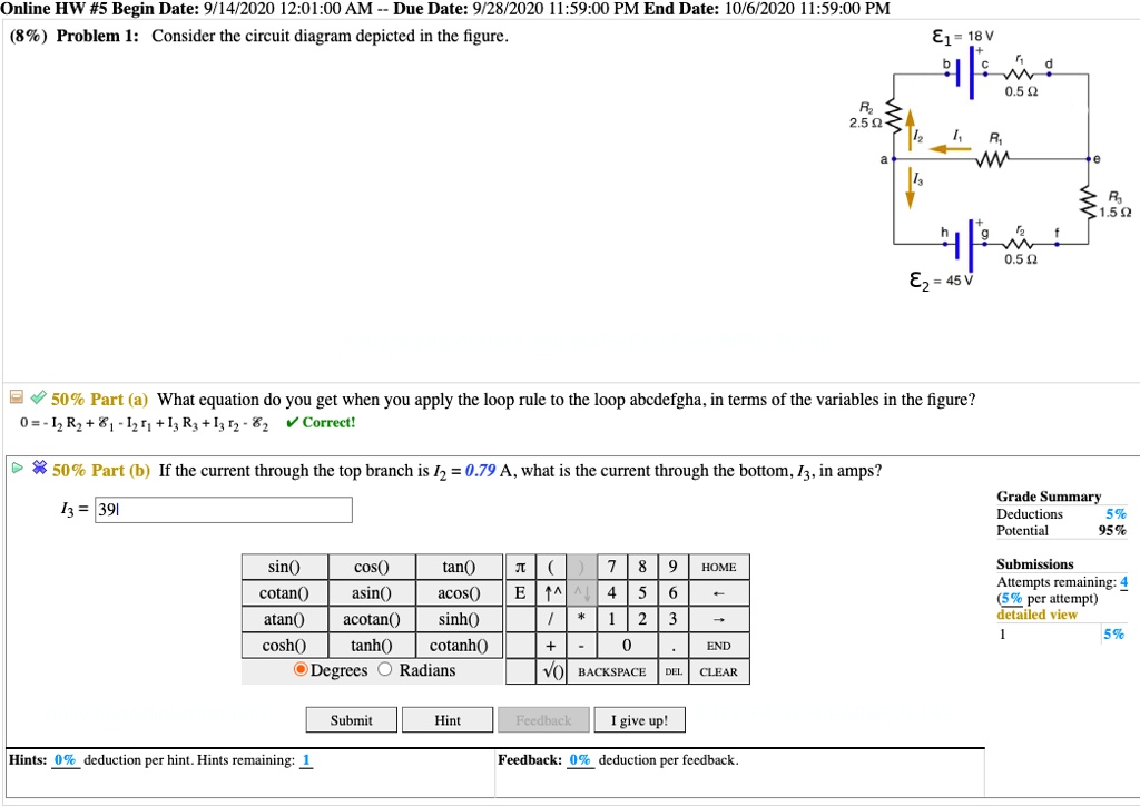
Solved:online hw #5 begin date: 9/14/2020 12.01.00 am due date: 9 ...

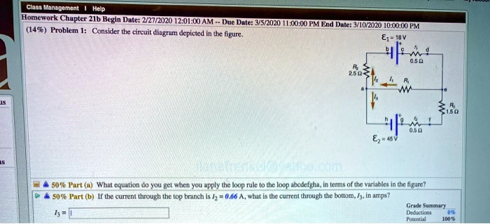
10) problem 1 consider the circuit diagram depicted in the figure ...
Solved consider the circuit diagram depicted in the figure ...

Energies | free full-text | experimental evaluation of an ...

The logic circuit diagram of 4 × 2 encoder. | download scientific ...

10) problem 1 consider the circuit diagram depicted in the figure ...

Passive and active topologies investigation for led driver ...

Energies | free full-text | realization of a generalized switched ...

10) problem 1 consider the circuit diagram depicted in the figure ...
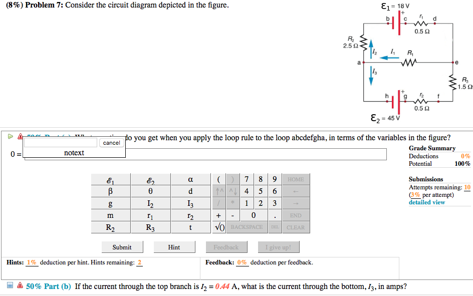
Solved (8%) problem 7: consider the circuit diagram depicted ...
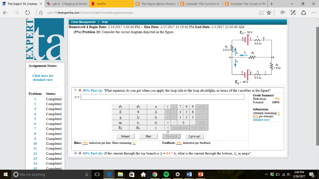
Solved:ciss wanzoltlent help homework chapter 21b bcgin dutc; 27 ...
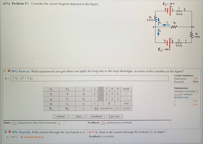
Solved (6%) problem 17: consider the circuit diagram | chegg.com
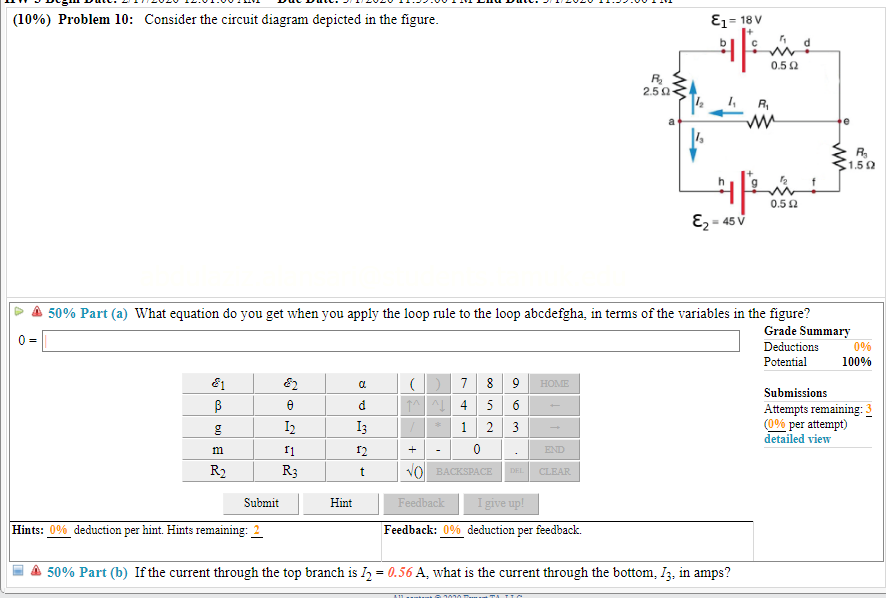
Solved (10%) problem 10: consider the circuit diagram | chegg.com
Solved consider the circuit diagram depicted in the figure ...
Solved consider the circuit diagram depicted in the figure ...
Solved:%) problem 4: consider the circuit diagram depicted in the ...
Answered: consider the circuit diagram depicted… | bartleby

Do-254 intro, compliance: free tools/ papers / resources - afuzion

Ideal current source - an overview | sciencedirect topics
Solved (10%) problem, 7: consider the circuit diagram | chegg.com
Solved the expert ta human. x e chegg study i guided solut ...
Solved l 2017 12:01:00 am due date: 2/17/2017 11:59:00 pm | chegg.com

Consider the circuit diagram depicted in the figure. a. what ...
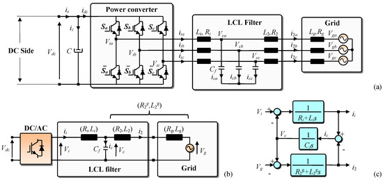
Energies | free full-text | an improved lcl filter design in order ...
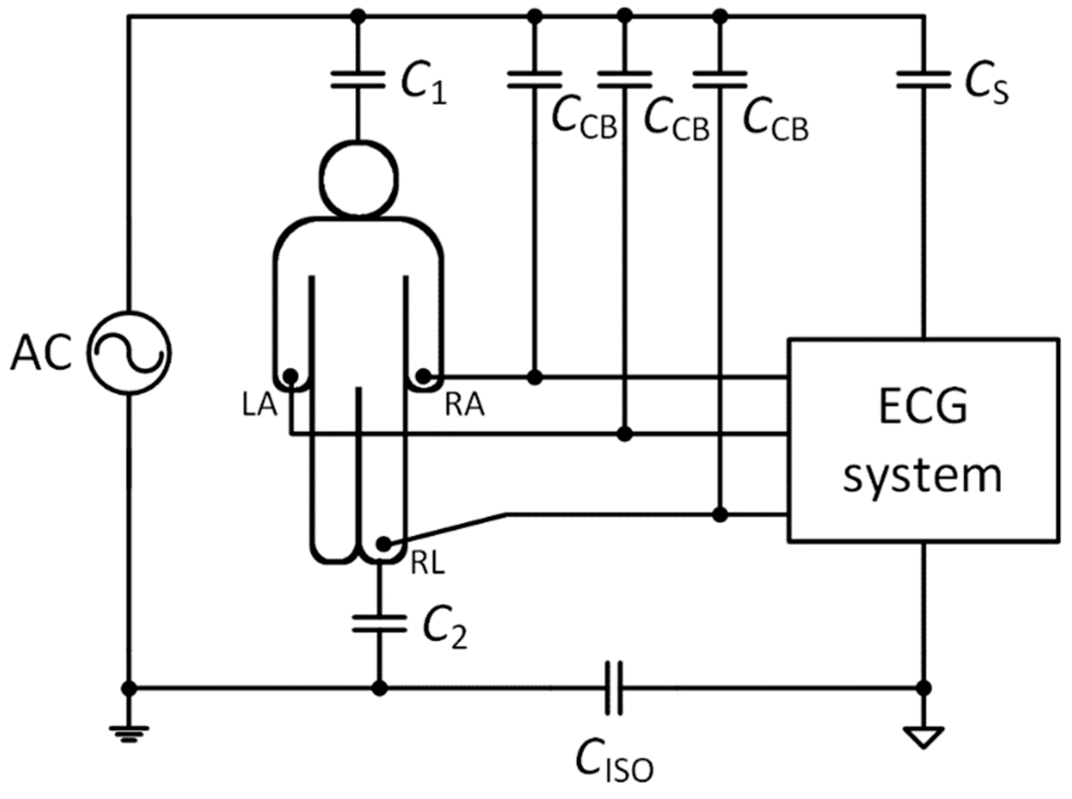
Sensors | free full-text | two-electrode ecg for ambulatory ...

Circuit diagram of proposed single-stage ac/dc converter with pfc ...
Consider the circuit diagram depicted in t... | clutch prep
0 Response to "42 consider the circuit diagram depicted in the figure."
Post a Comment