41 ansul hood wiring diagram
Kitchenhood Fire Contol With Ansul System Wiring Diagram. Interconnecting wire paths might be revealed around where certain receptacles or fixtures have to be on an usual circuit. Each part should be set and linked to other parts in specific manner.
I am wiring an ANSUL fire supression system and need to know how to tie the micro switches to the shunt trip breakers.I have two micro switches (v 20a) and two shunt breakers one v and one v and all i have to control is one v receptacle an exhuast hood (v) and one v intake fan.
Location. Massachusetts. Oct 29, 2013. #7. Seeing as we can no longer make control panels in the field* the customer should be purchasing a hood control panel that will have the proper connections for the fire panel, the ansul, the shut down etc. The wiring diagram will be specific to that.
Ansul hood wiring diagram
Ansul system wiring diagram ansul wiring diagram auto electrical wiring diagram credit. Is the least efficient diagram among the electrical wiring diagram. It shows the parts of the circuit as simplified forms and also the power and also signal connections in between the tools. What needs to connect to what and how to do it.
Wiring Diagram For Shunt Breaker In Fire Suppression System. The fire suppression system is master to the shut down of electrical equipment. The system will have a micro switch to activate a shunt trip breaker. gas valve must be *wired* so when exhaust fan is off gas is off-any wiring diagram? you said. A shunt trip breaker is a type of circuit ...
What needs to connect to what and how to do it.
Ansul hood wiring diagram.
Hood Ansul System Wiring Diagram | Manual E-Books - Ansul System Wiring Diagram. Wiring Diagram not merely provides comprehensive illustrations of what you can do, but additionally the processes you should adhere to while carrying out so. Not merely can you discover different diagrams, however, you also can get step-by-step guidelines for any ...
The ANSUL R-102 Restaurant Fire Suppression System is developed and tested to provide fire protection for restaurant cooking appliances, hoods, and ducts. It is a pre-engineered group of mechanical and electrical components for installation by an authorized ANSUL distributor. The basic system consists
8 Hood Sensor(s): To field-wire, connect low voltage wiring from the hood sensor terminals located in a junction box on end of hood, to sensor terminals S1 & S2 located in control panel. For a system controlling more than one hood, connect hood sensor #2 to S3 & S4, hood sensor #3 to S5 & S6, and hood sensor #4 to S7 & S8.
Ansul Hood Wiring Diagram Beautiful Ansul System Electrical Wiring Architectural wiring layouts reveal the approximate areas and also affiliations of receptacles, illumination, as well as permanent electric services in a building.
Hood Ansul System Wiring Diagram | Manual E-Books - Ansul System Wiring Diagram. Wiring Diagram not merely provides comprehensive illustrations of what you can do, but additionally the processes you should adhere to while carrying out so. Not merely can you discover different diagrams, however, you also can get step-by-step guidelines for any ...
ansul r wiring diagram including shunt trip ansul system together with ansul system fire alarm connection furthermore ansul hood wiring diagram. as specified in the ANSUL R Restaurant System Design, Installation, Recharge, and Maintenance Manual (Part WIRING DIAGRAM.
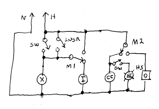
Ansul Hood System Schematic. Jump to Latest Follow 1 - 5 of 5 Posts ... See if you can locate the wire. It's an odd way to draw a diagram in my opinion The drawing has a large water mark distorting the bottom right. ... maybe trace the wiring back from the NO/NC micro switch in the fire suppression control head. I don't know if this helps or ...
Ansul Wiring Diagram. I have done a few but the Ansul guys always had a schematic. From an The suppression tech will also have the wiring diagram. When the. The field electrician is required to wire the following: 1. Fire System Micro Switch from the ANSUL or PYROCHEM Fire Suppression System connect wires. Label System (Wiring Diagram) Remote ...
By Jaris
Dc Power System Wiring Diagram Continued Tm 55 1520 240 T 2 511. 12 Restaurant Exhaust Hood System With Fans Fire Ele. Ansul hood system schematic wiring contractor talk r102 fire drawing commercial kitchen vent electrician 1 install one or two of the electrical i need help with an check knight ii general information contactors and 2 micro ...
ansul system wiring diagram - thanks for visiting my site, this article will review regarding ansul system wiring diagram. We have accumulated lots of images, ideally this photo is useful for you, as well as aid you in locating the response you are searching for. Description : Ansul R 102 Wiring Diagram - Facbooik for
Joined Jan 10, 2008. ·. 2,684 Posts. #20 · Jun 21, 2011. Only show this user. 99Kilowatt said: I got it fellas. Remove and install a shunt trip breaker for every electrical device under the hood. Run a low voltage wire from the 12v micro switch in the ansul system to the 12v shunt trips.
Piranha restaurant fire suppression systems
Commercial exhaust fan wiring diagram. Acvcr iom 2 b51003 003 for further information refer to the national elec trical code and the wiring diagram provided on the motor. Whole house ventilation type attic fans shall be permitted to discharge into the attic space of dwelling units having private attics.

Field wiring for the ansul snap-action switch, ansul wiring ...
Ansul Shunt Trip Wiring Diagram - wiring diagram is a simplified within acceptable limits pictorial representation of an electrical circuit. It shows the components of the circuit as simplified shapes, and the talent and signal connections amongst the devices. A wiring diagram usually gives recommendation just about the relative aim and ...
Hvacquick - how to's - wiring: 1 fan serving 2 baths with 1 ...
There are just two things that will be present in any Ansul System Wiring Diagram. The first element is symbol that indicate electrical component from the circuit. A circuit is usually composed by numerous components. The other thing you will see a circuit diagram could be traces.

Ansul system, fire suppression | pittsburgh, pa
ANSUL SAPPHIRE Clean Agent Fire Suppression System 2 with AUTOPULSE Z-10 Conventional Detection System B. The standards listed, as well as all other applicable codes, standards, and good engineering practices, shall be used as "minimum" design standards.

How to wire a ansul kitchen hood system
Need help to wire ansul system with 2 micro switch. When ansul is active -hood light & make up Air must off. & hood blower must on to sick out smoke . Please help the wiring diagram . Many thanks … read more

Ansul maintenance manual. (standard ul 300 listed) - pdf free ...
Captive Aire Hood Wiring Diagram Top Grade Of Ansul System. R 102 Restaurant Fire Suppression System. How to wire an Ansul system switch; has a common, NO and a NC Next, route a black or red wire from a single pole volt breaker to the common wire in the Ansul micro switch box. Please help the wiring diagram.
Kitchen
3. The hood light wiring will also need to be wired to terminals as indicated on the installation diagram. 4. If an ANSUL fire system is present, the fire system micro-switch will need to be wired to terminals as indicated on the installation diagram, typically "C1", "AR1". C1 is the common and connects to

Fire system microswitch wiring
A wiring diagram is a type of schematic which uses abstract pictorial symbols to reveal all the affiliations of parts in a system. The magic lung and power lung are whisper quiet and the most efficient blower systems available installation guides vent a hood. Before you purchase a range hood check the cfm rating of its fan.
Ansul wiring check | electrician talk
Kitchenhood Fire Contol With Ansul System Wiring Diagram Exhaust and supply fans are interlocked and fire suppression system activated, as required from breaker panel to control panel for fans (see wiring diagram.). ( mm) deep by the length of the cooking hazard (s).

R-102 intro rev record | manualzz
Ansul System Wiring Diagram On Maxresdefault Wiring Diagram inside Ansul System Wiring Diagram. It is a pre-engineered group of mechanical and electrical components for installation by an authorized ANSUL distributor. Ad Encuentra Fire Suppression System. The wiring on the system. Kitchenhood Fire Contol With Ansul System Wiring Diagram.

Page 15 of broan ventilation hood e60000 series user guide ...
Ansul R 102 Wiring Diagram. The hood light wiring will also need to be wired to terminals as indicated on the installation diagram. Exhaust and supply fans are interlocked and fire suppression system activated supply fan s shut 1 or 3 phase power as required from breaker panel to.
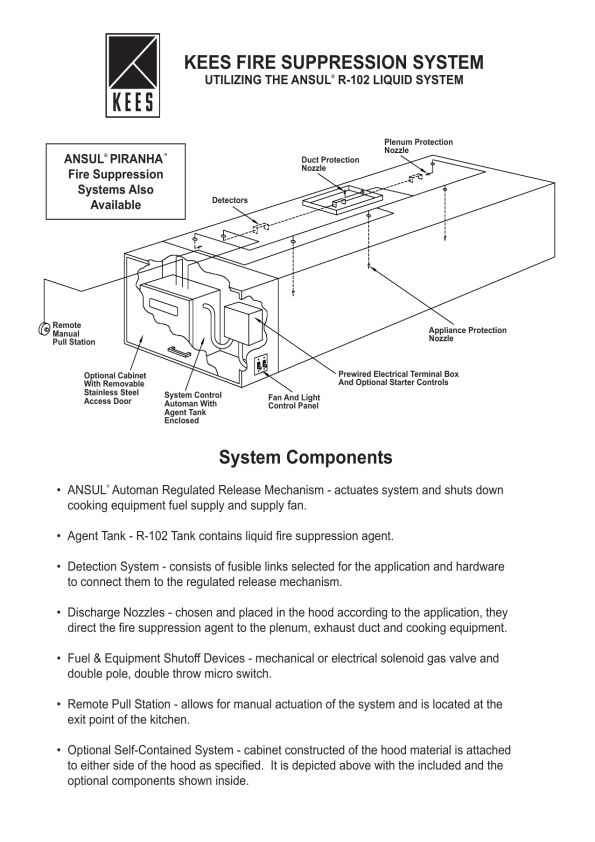
Kees fire suppression system system components | manualzz
Commercial Vent Hood Wiring Diagram Sample. commercial vent hood wiring diagram - Building circuitry layouts reveal the approximate locations and also interconnections of receptacles, lighting, and irreversible electric solutions in a building. Interconnecting wire paths might be revealed around, where certain receptacles or fixtures have to be on an usual circuit.

I have the need to operate an ansul system using contactors ...
Operators manual
Ansul hood system schematic | electrician talk

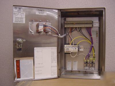
Electrical wiring-fire control box
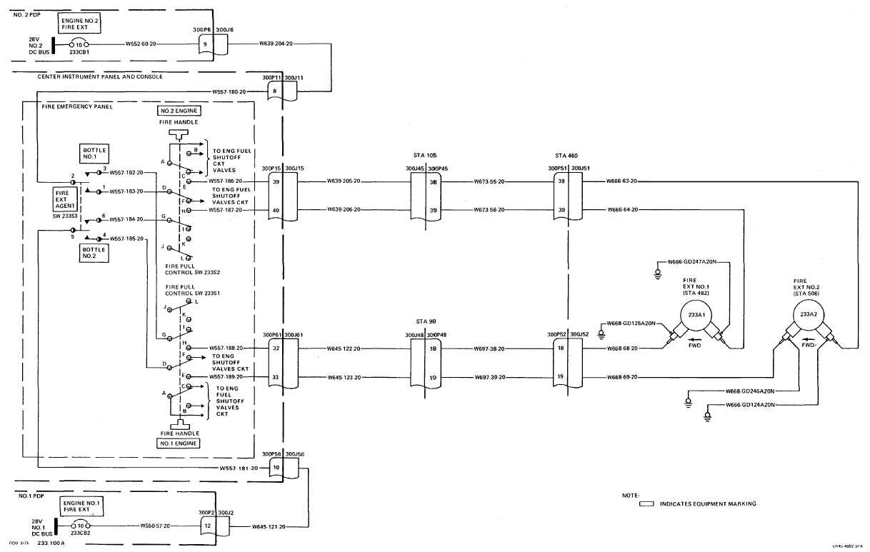
Fire extinguishing system wiring diagram

Kitchen suppression buckeye
Ventless exhaust hoods
12' restaurant exhaust hood system with fans, fire, ele

Fire suppression systems, maintenance, installation and ...

I need a wiring diagram for a commercial kitchen vent hood
Ansul system wiring | contractor talk - professional ...

Fire systems named ansul diamond distributor for second ...

Need help wiring this fire system : r/electricians
Ansul system interlock? | electrician talk
Critique my diagram. | page 2 | mike holt's forum

I need a wiring diagram for a commercial kitchen vent hood

Small - 5f pre-packaged fire suppression system ...
Kitchen knight ii - general information

I need a wiring diagram for a commercial kitchen vent hood
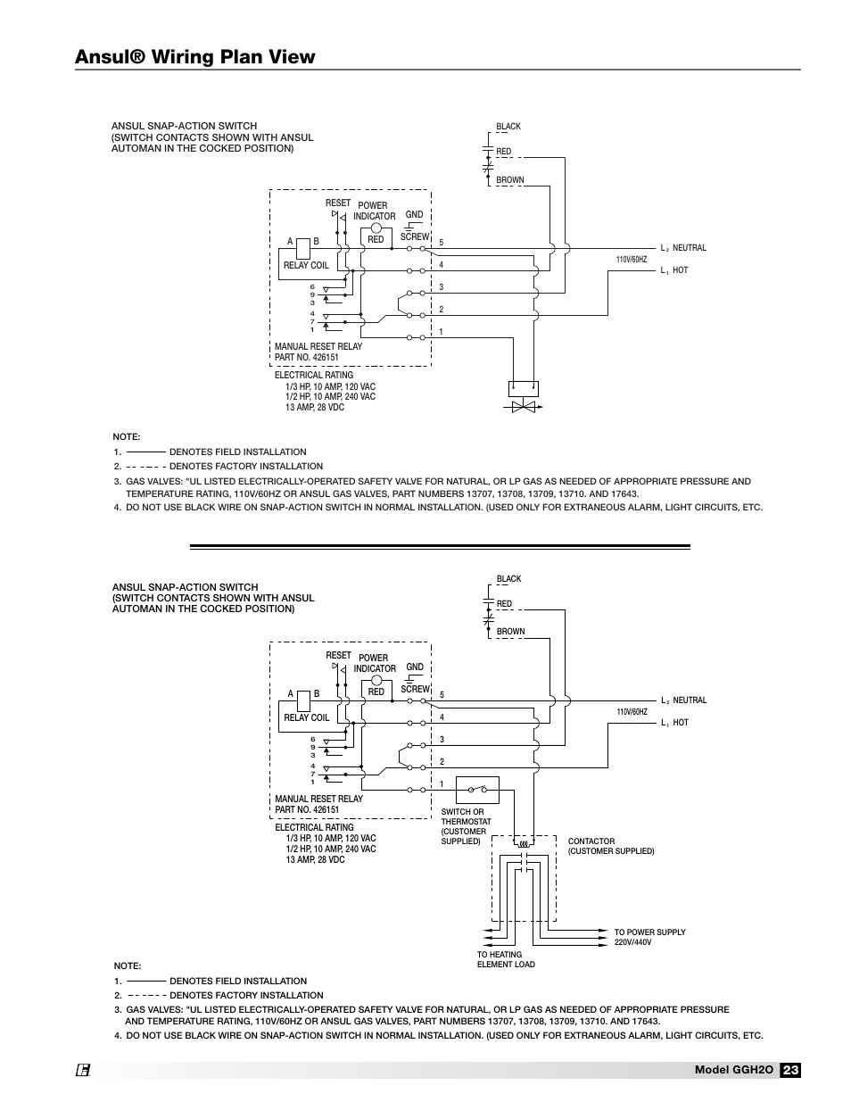
Ansul® wiring plan view | greenheck fan grease grabber h2o ...
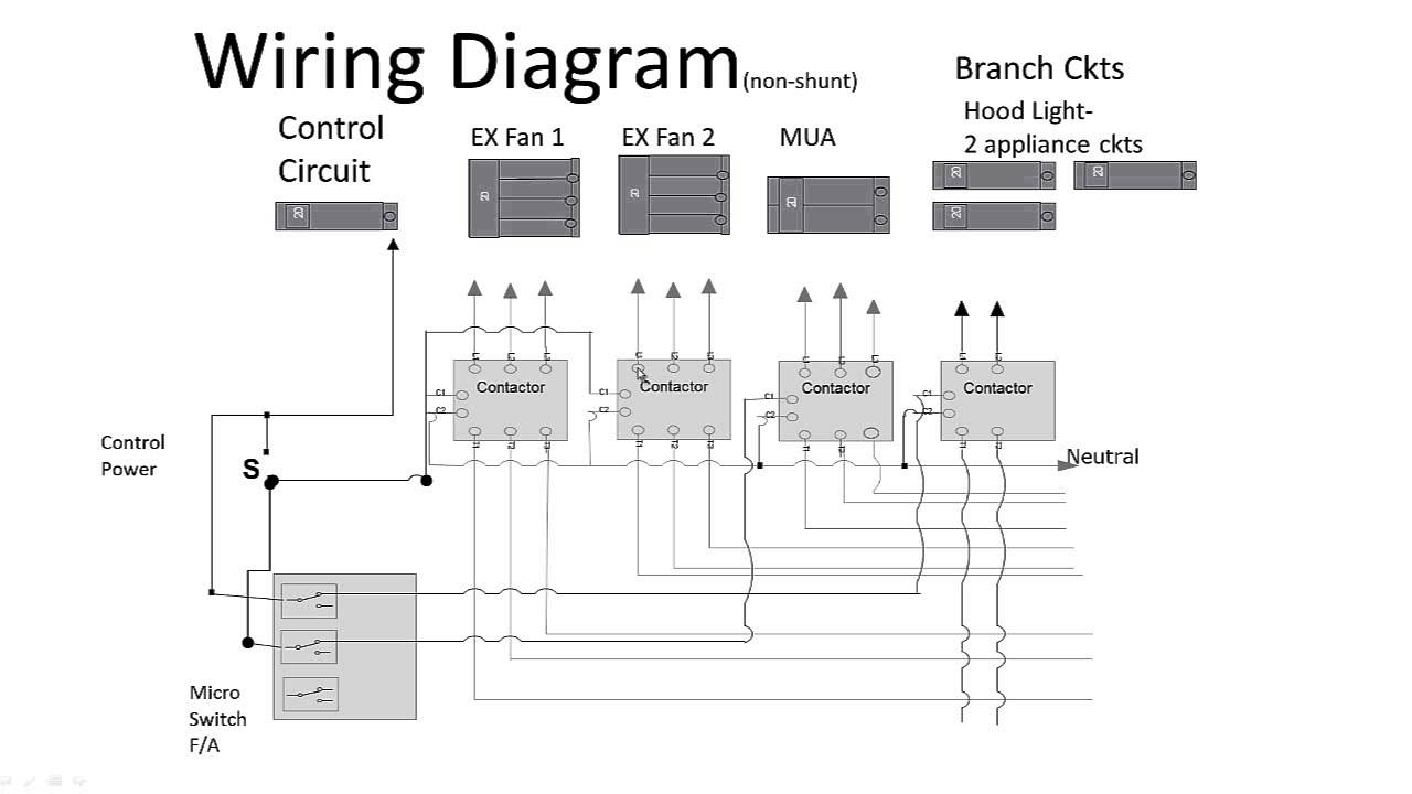
Kitchen hood non-shunt trip
Seberapa sulit memasang tudung jangkauan jika tidak ada ...

Engine coolant temperature sensor circuit diagram - wiring ...

Pramod kumar (nrcons) - profile | pinterest

Product detail
Ansul system | electrician talk
Kitchen hood - shunt trip breakers required. | mike holt's forum
Ansul r102 fire system drawing
0 Response to "41 ansul hood wiring diagram"
Post a Comment