44 draw a ray diagram for the following situation involving a converging lens
Draw a ray diagram for the following situation an object far from the lens. B use a ruler to measure the object distances image distances and focal lengths for the ray diagram. Ray diagrams for images made by a convex lens. Further down the page there is a picture showing. For a magnifying lens to work the object is placed close to the convex lens ie. between the lens and the focal point. Draw a ray diagram to show how such a lens would work. Hint: you need to label both the object and image in your diagram and to think about where the image appears to be.
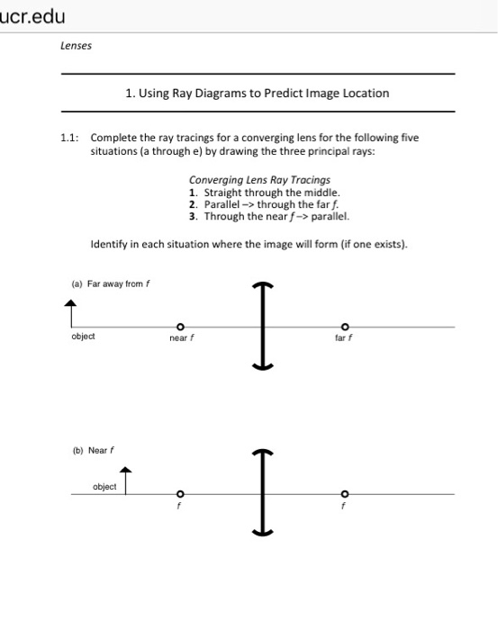
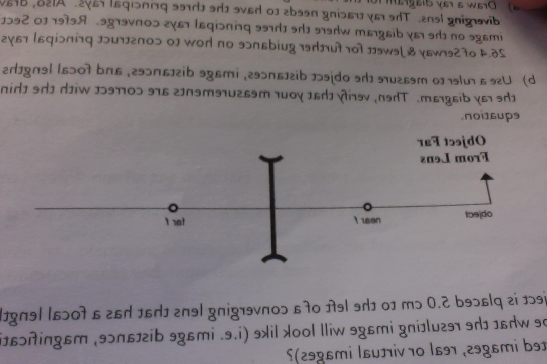
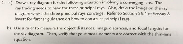
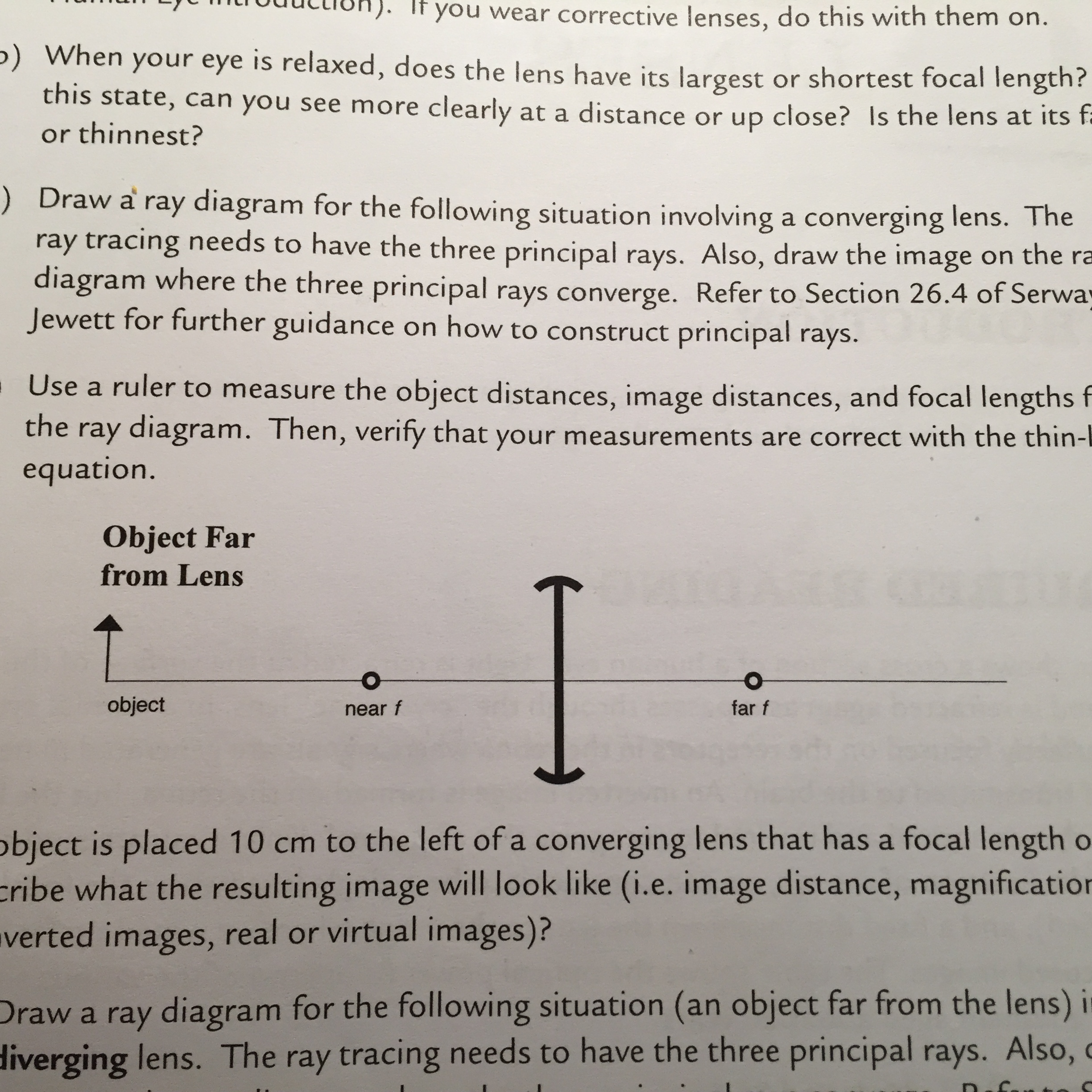
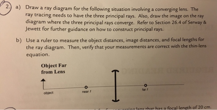
Question: a) Draw a ray diagram for the following situation involving a converging lens. The ray tracing needs to have the three principal rays. Also, draw the image on the ray diagram where the three principal rays converge. b) Use a ruler to measure the object distances, image distances, and focal lengths for the ray diagram.
Draw a ray diagram for the following situation involving a converging lens
Also draw the image on the ray ... waves converge. B) Use a ruler to measure the object distances, image distances, and focal lengths for the ray diagram. Then verify that your measurements are correct with the thin-lens equation. 4. a) Draw a ray diagram for the following situation ... Transcribed image text: Draw a ray diagram for the following situation involving a converging lens. The ray tracing needs to have the three principal rays. Also ... Draw a ray diagram for the following situation (an object far from the lens) involving a diverging lens. The ray tracing needs to have the three principal rays. Also, draw the image on the ray diagram where the three principal rays converge. Refer to Section 26.4 of Serway & Jewett for further guidance on how to construct principal rays.
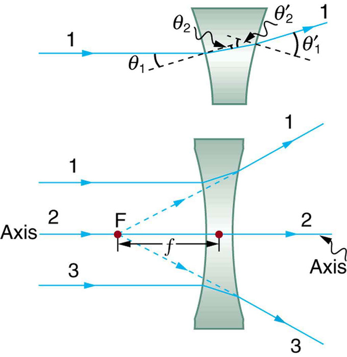
Draw a ray diagram for the following situation involving a converging lens. (The axis is defined to be a line normal to the lens at its center, as shown in Figure 1.) Such a lens is called a converging (or convex) lens for the converging effect it has on light rays. An expanded view of the path of one ray through the lens is shown, to illustrate how the ray changes direction both as it enters and as it leaves the lens. A draw a ray diagram for the following situation an object far from the lens involving a diverging lensthe ray tacing needs to have the three principal raysalso draw the image on the ray diagram where the three principle waves converge. Parallel to the principal axis of the lens. From the tip of the object arrow. A draw a ray diagram for the following situation an object far from the lens involving a diverging lensthe ray tacing needs to have the three principal raysalso draw the image on the ray diagram where the three principle waves converge. Refer to section 264 of serway jewett for further guidance on how to construct principal rays. The a ray tracing needs to have the three principal rays. Draw a ray diagram for the following situation an object far from the lens. Extend both rays as much as you can line in blue. Ray diagrams 3 of 4 concave and convex lenses and mirrors. Parallel light rays duration. Start by drawing the ray parallel to the optical axis from the object incident ...
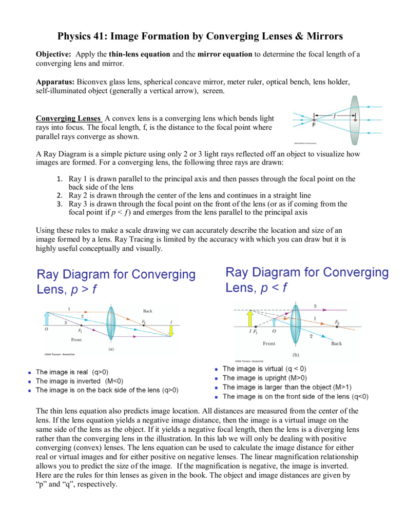
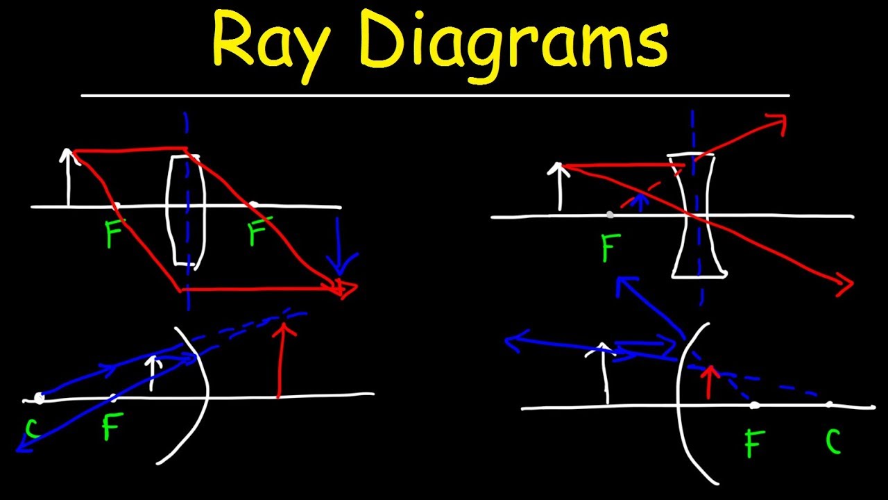
Draw a ray diagram for the following situation involving a converging lens. The ray tracing needs to have the three principal rays. Also, draw the image on the ray diagram where the three principal rays converge. Refer to Section 26.4 of Serway & Jewett for further guidance on how to construct principal rays. Use a ruler to measure the object distances, image distances, and focal lengths for ... A Ray Diagram is a simple picture using only 2 or 3 light rays reflected off an object to visualize how images are formed. For a converging lens, the following three rays are drawn: 1. Ray 1 is drawn parallel to the principal axis and then passes through the focal point on the back side of the lens 2. Problem: A) Draw a ray diagram for the following situation (an object far from the lens) where the three principle waves converge.B) Use a ruler to measure the object distances, image distances, and focal lengths for the ray diagram. Then verify that your measurements are correct with the thin-lens ... Draw a ray diagram for the following situation involving a diverging lens. Support my channel by doing all of the following. As shown above real images are produced when the object is located a distance greater than one focal length from the lens. The ray tacing needs to have the three principal rays. The image point of the top of the object is the point where the three refracted rays ...
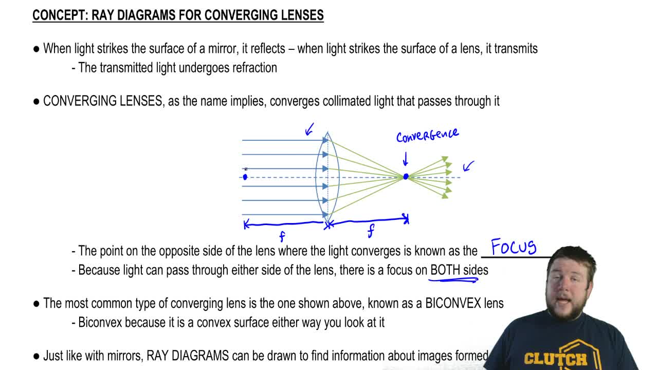
The method of drawing ray diagrams for double convex lens is described below. The description is applied to the task of drawing a ray diagram for an object located beyond the 2F point of a double convex lens. 1. Pick a point on the top of the object and draw three incident rays traveling towards the lens. Using a straight edge, accurately draw ... To explain how to draw the diagrams, there are two key things to remember. 1 A converging lens refracts the light so that any ray of light parallel to the principal axis (the thick horizontal line) is turned to pass through the focal point. Rays of light parallel to the principal axis are all refracted through the focal point. A lens is basically a carefully grounded piece of transparent material which refracts light rays in such a way as to form an image. There are two types of lenses: Convex Lens (Converging) and Concave Lens (Diverging). A converging lens causes light rays that are parallel to the principal axis to converge or meet, at one point (the principal focus). Rule 2 - Ray passing through focus will become parallel to principal axis after reflection. For a concave mirror , we see that ray passing through focus becomes parallel to principal axis after reflection. For a convex mirror, since focus is on the right side, it appears that ray passes through focus, and then it becomes parallel to principal axis.
Solved Ucr Edu Lenses 1 Using Ray Diagrams To Predict Image Chegg Com
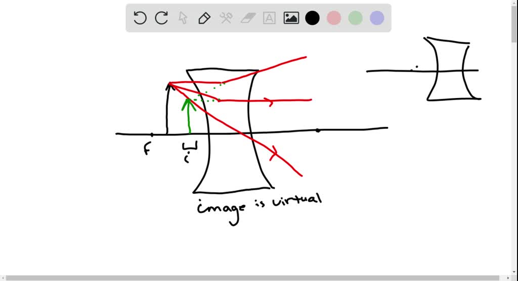
Draw a ray diagram for the following situation involving a diverging lens. Using a straight edge extend each of the rays using dashed lines. While diverging lenses always produce virtual images converging lenses are capable of producing both real and virtual images.

7 Draw A Ray Diagram For The Following Situation And Use It To Determine The Location Homeworklib
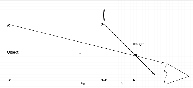
In order to draw a ray diagram, take two rays of light from the object. Ray 1: A ray parallel to the principal axis . Ray 2: A ray passing through the pole . After reaching the lens, ray 1 will bend and pass through the focus. Ray 2 will pass without any deviation. The two rays will converge at a point and recreate an image.

Ray Diagrams Converging Lenses Youtube
A draw a ray diagram for the following situation an object far from the lens involving a diverging lens. Step by step method for drawing ray diagrams. If an object is located between the focal point and converging lens the image will be. Through the center of the lens. Also draw the image on the ray diagram where the three principal rays converge.
Solved A 15 Cm Tall Object Is Placed 25 Cm Away From A Converging Lens With A Focal Length Of 15 Cm Draw A Ray Diagram To Scale Use The Following Scale 5
Question: a) Draw a ray diagram for the following situation involving a converging lens. The ray tracing needs to have the three principal rays. Also, draw the image on the ray diagram where the three principal rays converge. b) Use a ruler to measure the object distances, image distances, ...

New Page 1
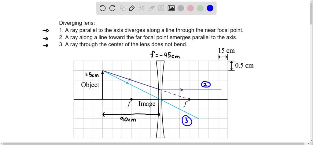
a) Draw a ray diagram for the following situation (an object far from the lens) involving a diverging lens. The ray tracing needs to have the three principal rays. Also, draw the image on the ray diagram where the three principal rays converge. Refer to Section 26.4 of Serway & Jewett for further guidance on how to construct principal rays.

A Draw A Ray Diagram For The Following Si Clutch Prep
A real object is placed to the right of a converging lens at a distance 2f. The focal length of the lens is f. By carefully drawing a ray diagram for this situation, determine which of the following statements best describes the image formed.
Solved A Draw A Ray Diagram For The Following Situation An Chegg Com
Draw a ray diagram for the following situation involving a converging lens. The ray tracing needs to have the three principal rays. Also, draw the image on the ...
Draw A Ray Diagram For The Following Situation Chegg Com
Now, we draw the ray diagram as follows: (i) Draw a horizontal line to represent the principal axis of the convex lens. (ii) Centre line is shown by DE. (iii) Mark two foci F and F' on two sides of the lens, each at a distance of 2 cm from the lens. (iv) Draw an arrow AB of height 1 cm on the left side of lens at a distance of 5 cm from the lens.

16 3 Lenses Texas Gateway
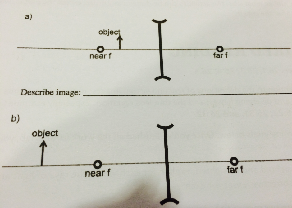
A) Draw a ray diagram for the following situation (an object far from the lens) involving a diverging lens.The ray tacing needs to have the three principal rays.Also draw the image on the ray diagram where the three principle waves converge.. B) Use a ruler to measure the object distances, image distances, and focal lengths for the ray diagram.
Lenses Boundless Physics
a) draw a ray diagram for the following situation (an object far from the lens) involving a diverging lens. The ray tacing needs to have the three principal ...

A Draw A Diagram To Show How A Converging Lens Focusses Parallel Rays Of Light B How Would You Alter The Above Diagram To Show How A Converging Lens Can Produce A
the lens. Ray diagrams can be a useful tool for analyzing the behavior of light rays passing through thin lenses. Here are some rules for drawing light rays in ray diagrams. 1. A light ray approaching the lens parallel to the principle axis will pass through the focal point on the opposite side of the lens for a

A Draw The Ray Diagram To Show How The Images Of The Object Will Form Behind Homeworklib
(a) Draw a ray diagram for the following situation involving a converging lens. The ray-tracing needs to have three principal rays. Also, draw the image on the ray diagram where the three principal rays converge. (b) Use the ruler to measures the object distances, image distances, and focal lengths of the ray diagram. then, verify that your ...
Cyberphysics Rules For Drawing Ray Diagrams
Draw a ray diagram for the following situation involving a diverging lens. As shown above real images are produced when the object is located a distance greater than one focal length from the lens. Ray tracing concave diverging lens worked example. Ray diagram for object located in front of the focal point. Ray diagrams for converging lenses duration. This is the type of information that we ...
Draw A Ray Diagram For A Converging Lens W Clutch Prep
Draw a ray diagram for the following situation involving a diverging lens. Also draw the image on the ray diagram where the three principal rays converge. Since the three refracted rays are diverging they must be extended behind the lens in order to intersect.

Draw A Ray Diagram For The Following Situation An Object Far From The Lens Involving A Homeworklib
A) Draw a ray diagram for the following situation ( an object far from the lens) involving a diverging lens. The ray tracing needs to have the three principal rays. B) Use a ruler to measure the object distances, image distances, and focal lengths for the ray diagram. Then verify that your measurements are correct with the thin-lens equation.
Ray Diagrams For Lenses
Ray Diagrams for Lenses. The image formed by a single lens can be located and sized with three principal rays. Examples are given for converging and diverging lenses and for the cases where the object is inside and outside the principal focal length. The "three principal rays" which are used for visualizing the image location and size are:

Image Formation By Lenses Physics
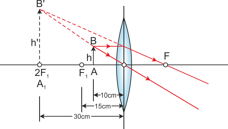
9. An object is placed 30 cm from a converging lens that has a focal length of 10 cm. Make a ray diagram of this situation. From the ray diagram, characterize the image. The image is. a) real, inverted, and larger. b) real, inverted, and smaller. c) virtual, upright, and smaller. d) virtual, inverted, and smaller. 10. An object is placed 15 cm ...
Draw A Ray Diagram For The Following Situation An Object Far From The Lens Atkinsjewelry
Draw a ray diagram for the following situation involving a diverging lens. Diverging lenses ray 1. The ray diagram above illustrates that the image of an object in front of a double concave lens will be located at a position behind the double concave lens. Also draw the image on the ray diagram where the three principal rays converge. B use a ruler to measure the object distances image ...
Solved Draw A Ray Diagram For The Following Situation Suppose We Have Simple Microscope Which Has A Double Lens Find The Magnification Focal Length For 1 And 2 The Image Distance For 1
(b) What is the focal length of the lens? (c) Locate the image by drawing the other two principal rays. (d) Calculate where the image should be, and compare ...4 answers · Top answer: All right, So this is similar to problem 54. From the diagram, we see that the ray is bending ...

A Draw The Ray Diagram To Show How The Images Of The Object Will Form Behind Homeworklib
Problem: A) Draw a ray diagram for the following situation (an object far from the lens) where the three principle waves converge.B) Use a ruler to measure ...1 answer · Top answer: Lens equation: 1so+1si=1fThe three principal rays used in ray tracing include:1. An incident ray traveling parallel to the principal axis of a converging ...
2
Ray Diagram for Object Located in Front of the Focal Point. In the three cases described above - the case of the object being located beyond 2F, the case of the object being located at 2F, and the case of the object being located between 2F and F - light rays are converging to a point after refracting through the lens. In such cases, a real image is formed.
Solved A Draw A Ray Diagram For The Following Situation Chegg Com
24-8 An Example Problem Involving a Lens Let's begin by discussing a general approach we can use to solve problems involving a lens. We will then apply the method to a particular situation. A general method for solving problems involving a lens 1. Sketch a ray diagram, showing rays leaving the tip of the object and being refracted by the lens.

Igcse Physics Unit 3 Properties Of Waves
These three rules will be used to construct ray diagrams. A ray diagram is a tool used to determine the location, size, orientation, and type of image formed by a lens. Ray diagrams for double convex lenses were drawn in a previous part of Lesson 5. In this lesson, we will see a similar method for constructing ray diagrams for double concave ...
Lab 9 Ray Diagrams
First, we draw a ray parallel to principal axis. So, it passes through focus after refraction. We draw another ray which passes through Optical Center. So, the ray will go through without any deviation. Where both rays meet is point A'. And the image formed is A'B'. This image is formed between F 2 and 2F 2. We can say that.
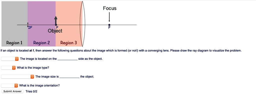
Solved Focus Object Region Region 2 Region 3 If An Object Located At Then Answer The Following Questions About The Image Which Formed Or Notl With Converging Lens Please Draw The Ray Diagram
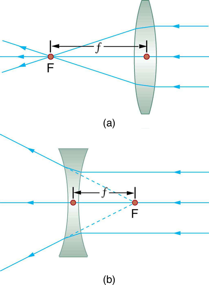
Convex (converging) and concave (diverging) lenses are drawn as, V W To understand image formation we use ray diagrams. Here is an example for aconvex lens: F The image of the top of the object is formed where the light rays cross. In a perfect lens all the rays from a point on the object will meet at one other point - so we only need to draw ...
1
Ray diagrams help us trace the path of the light for the person to view a point on the image of an object. Ray diagram uses lines with arrows to represent the incident ray and the reflected ray. It also helps us trace the direction in which the light travels. Plane Mirror vs Spherical Mirrors
1
a) Draw a ray diagram for the following situation involving a converging lens. The a) ray tracing needs to have the three principal rays. Also, draw the image on the ray diagram where the three principal rays converge. Refer to Section 26.4 of Serway & Jewett for further guidance on how to ...

Draw A Ray Diagram In Each Of The Following Cases To Show The Formation Of Image When The Object Is Placed I Between Optical Centre And Principal Focus Of A Convex Lens Ii
A draw a ray diagram for the following situation an object far from the lens involving a diverging lens. While diverging lenses always produce virtual images converging lenses are capable of producing both real and virtual images. As shown above real images are produced when the object is located a distance greater than one focal length from the lens.

Ray Diagrams Lenses Physics Lab Video Lesson Transcript Study Com
11 draw a ray diagram for a diverging lens that has a focal length of 108 cm when an object is placed 324 cm from the lenss surface. 2 rays are enough to determine the position of imageobject. 122 ray diagrams lenses in this video paul andersen explains how ray diagrams for lenses can be used to determine the size and location of a refracted image.
Rules Of Drawing Ray Diagram In Lens Qs Study
Draw a ray diagram for the following situation (an object far from the lens) involving a diverging lens. The ray tracing needs to have the three principal rays. Also, draw the image on the ray diagram where the three principal rays converge. Refer to Section 26.4 of Serway & Jewett for further guidance on how to construct principal rays.
Ray Diagrams For Lenses
Transcribed image text: Draw a ray diagram for the following situation involving a converging lens. The ray tracing needs to have the three principal rays. Also ...

Draw The Ray Diagram For The Converging Lens When The Object Distance Is Larger Than The Focal Length And Also With Object Distance Smaller Than The Focal Length Study Com
Also draw the image on the ray ... waves converge. B) Use a ruler to measure the object distances, image distances, and focal lengths for the ray diagram. Then verify that your measurements are correct with the thin-lens equation. 4. a) Draw a ray diagram for the following situation ...
Physics Tutorial Refraction And The Ray Model Of Light
Solved 2 A Draw A Ray Diagram For The Following Situation Chegg Com
Qrpastpapers Com
The Following Diagram In Fig 5 57 Shows An Object Ab And A Converging Lens L With Foci F1 And F2 Sarthaks Econnect Largest Online Education Community

Where Do The Three Rays In A Ray Diagram Start Wiring Site Resource
1

Q38 Draw A Ray Diagram To Show Lido
A Draw A Ray Diagram For The Following Si Clutch Prep
Lenses Boundless Physics
Ray Diagrams Youtube

A Converging Lens With Virtual Image The Students Had To Show That Download Scientific Diagram
Two Situations Involving Objects And Diver Clutch Prep
0 Response to "44 draw a ray diagram for the following situation involving a converging lens"
Post a Comment