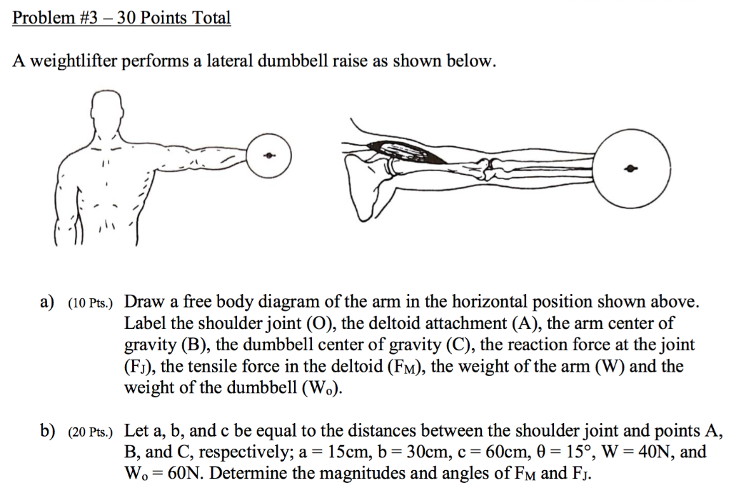
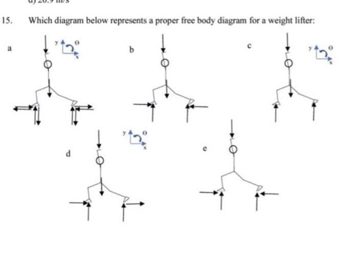
43 draw a free-body diagram for the weight lifter.
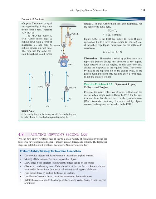
Figure 5.32 (a) The free-body diagram for isolated object A. (b) The free-body diagram for isolated object B. Comparing the two drawings, we see that friction acts in the opposite direction in the two figures. Because object A experiences a force that tends to pull it to the right, friction must act to the left. Because object B experiences a component of its weight that pulls it to the left ... FREE-BODY DIAGRAMS (Section 5.2) 2. Show all the external forces and couple moments. These typically include: a) applied loads, b) support reactions, and, c) the weight of the body. Idealized model Free-body diagram (FBD) 1. Draw an outlined shape. Imagine the body to be isolated or cut "free" from its constraints and draw its outlined shape.
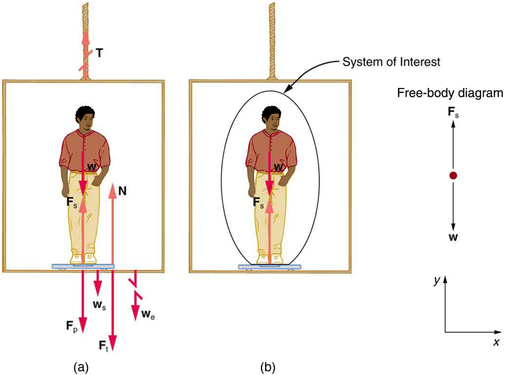
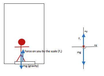
Your free-body diagram has two forces, the force of gravity and the upward normal force from the elevator. The elevator's free-body diagram has three forces, the force of gravity, a downward normal force from you, and an upward force from the tension in the cable holding the elevator.

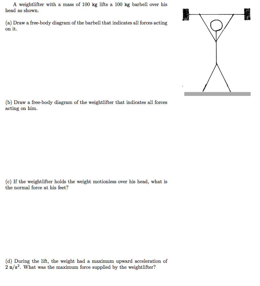
Draw a free-body diagram for the weight lifter.
Examples of drawing free-body diagrams. To better understand how to draw free-body diagrams using the 3 steps, let's go through several examples. Example 1. A box is pushed up an incline with friction which makes an angle of 20 ° with the horizontal. Let's draw the free-body diagram of the box. The first step is to sketch what is happening: It looks like many lamps found all over the world. The three photos illustrate how the free body diagram for this structure should be conceived. The first step is to dematerialize the lamp. Identify the center of the body and draw this as a straght line. The only identifieable weight is the lamp, so this is drawn as a vector as indicated. Free-Body Diagram 4 - 4 The first step in the static equilibrium analysis of a rigid body is identification of all forces acting on the body with a free body diagram. • Select the body to be analyzed and detach it from the ground and all other bodies and/or supports. • Include the dimensions, which will be needed
Draw a free-body diagram for the weight lifter.. Free Body Diagram - 941 Words | Cram. Show More. Check Writing Quality. Register to read the introduction…. Move the ramp to an angle of zero (horizontal) and draw a free body diagram of the cabinet here: On a horizontal plane, the normal force is _Perpendicular_______ to the weight. The cabinet has a mass of 100kg. Academia.edu is a platform for academics to share research papers. 3) Draw the kinetic diagram of the crate: The crate will be pulled to the right. The acceleration vector can be directed to the right if the truck is speeding up or to the left if it is slowing down. 2) Draw the free-body diagram of the crate: The weight force (W) acts through the crate's center of mass. T is the tension force in the cable. Homework Statement A weightlifter stands up at constant speed from a squatting position while holding a heavy barbell across his shoulders. Draw the free body diagram of the lifer using F g, normal force, and force by barbell Homework Equations
A. Draw a free-body diagram representing the raft for each situation. B. Find the force exerted by each lifeguard on the raft for each situation. (Disregard any other forces acting on the raft). A. F1 (220 N) and F2 (114 N) both point right; F1 (220 N) points left, and F2 (114 N) points right B. first situation: 220 N to the right, 114 N to the ... To draw a free body diagram, start by sketching a simple representation of the body you want to make the diagram of, like a square to represent a box. Next, draw arrows on the shape that show the forces acting on the object. For example, draw a downward arrow to signify the weight of the object, since gravity pulls the object down. •Normal Force (more weight on top of book ↑ ... Draw a free-body diagram showing the forces involved. Gravity is the only force acting on the egg as it falls. Problem 3 A flying squirrel is gliding (no wing flaps) from a tree to the ground at constant velocity. Consider air resistance. A free (a) Draw a free-body diagram for the beam. (b) When the bear is at x = 1.00 m, find the tension in the wire and the components of the force exerted by the wall on the left end of the beam. (c) If the wire can withstand a maximum tension of 900 N, what is the maximum distance the bear can walk before the wire breaks?
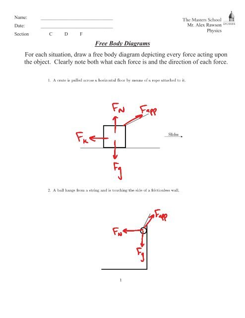
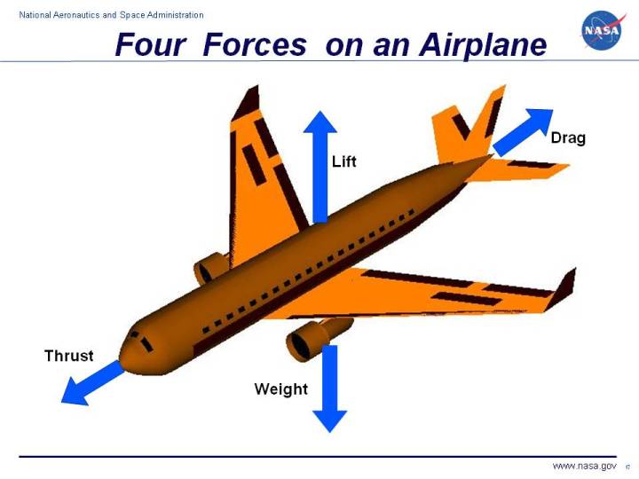
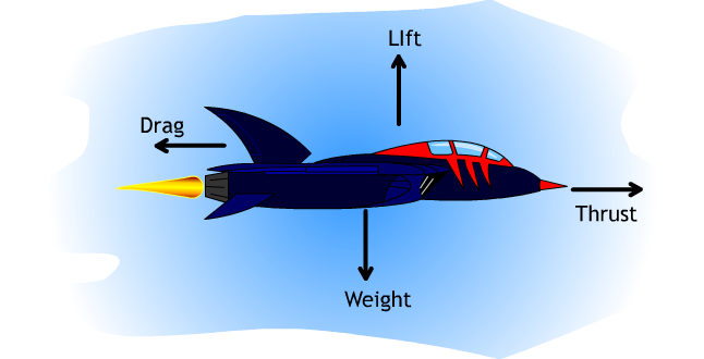
Counterweight in lift Drawing Free-Body Diagrams. Free-body diagrams are diagrams used to show the relative magnitude and direction of all forces acting upon an object in a given situation. A free-body diagram is a special example of the vector diagrams that were discussed in an earlier unit. These diagrams will be used throughout our study of physics. Commonly used forces in free body diagrams are weight (Fg), friction including air resistance (Ff), normal force supplied by a surface (FN), and applied force (Fa). Components of forces are often labeled (Fx) or (Fy). Questions. 1. Draw a free body diagram of a parachutist who . a. has just stepped out of the airplane, and is accelerating ... A) free body diagram for block m 1 (left of figure below) 1) The weight W 1 exerted by the earth on the box. 2) The normal force N 3) The force of friction F k 4) The tension force T exerted by the string on the block m 1. B) free body diagram of block m 2 (right of figure below) 1) The weight of the block W 2 2) Tension T '.
Figure 5.32 (a) The free-body diagram for isolated object A. (b) The free-body diagram for isolated object B. Comparing the two drawings, we see that friction acts in the opposite direction in the two figures. Because object A experiences a force that tends to pull it to the right, friction must act to the left. Because object B experiences a component of its weight that pulls it to the left ...
Level 3: Drawing Free Body Diagrams When we are working with forces, we often need to find the net force acting on an object. To do this, we first start by sketching a picture of the forces acting on it. We call this picture a free body diagram. There are a few rules we should follow when drawing a free body diagram. 1.
Draw a free-body diagram for the barbells. Draw the force vectors with their tails at the dot. The orientation of your vectors will be graded. The exact length of your vectors will not be graded but the relative length of one to the other will be graded. ANSWER: Correct Part B Draw a free-body diagram for the weight lifter.
Draw a free body diagram for the weight lifter. Draw the force vectors with their tails at the dot. The orientation of your vectors will be graded. The exact length of your vectors will not be graded but the relative length of one to the other will be graded. A weightlifter stands up at constant speed from a squatting position while holding a ...
Because the weight is evenly distributed between the hinges, we have the fourth equation, [latex]{A}_{y}={B}_{y}.[/latex] To set up the equilibrium conditions, we draw a free-body diagram and choose the pivot point at the upper hinge, as shown in panel (b) of Figure. Finally, we solve the equations for the unknown force components and find the ...
Academia.edu is a platform for academics to share research papers.
It is connected to a lead weight (m 2 = 100 g) suspended vertically off the end of a pulley as shown in the diagram below. The system is released and the cart accelerates to the right. (Assume the string and pulley contribute negligible mass to the system and that friction is kept low enough that it can be ignored.) Draw a free body diagram for…
A Mercedes-Benz 300SL (m = 1715 kg) is parked on a road that rises 10 degrees above the horizontal. Friction is not zero. (a) Draw a free body diagram of the car, including all the forces. (b) Writ...
The free body diagram is the most fundamental aspect of structural engineering. If you cannot draw a free body diagram, you are not cutout to be a structural engineer. That being said, if you struggle with free body diagrams that's perfectly fine. I can help get you up to speed.
A weight lifter stands on a bathroom scale. (a) As she pumps a barbell up and down, what happens to the reading on the scale? ... Draw a free body diagram for each of ...
Free-Body Diagram.The x, y, z axes are established at B and the free-body diagram of segment AB is shown in Fig. 1-8b.The resultant force and moment components at the section are assumed to act in the positive coordinate directions and to pass through the centroid of the cross-sectional area at B. The weight of each segment of pipe is
A weightlifter stands up at constant speed from a squatting position while holding a heavy barbell across his shoulders. Draw a free-body diagram for the weight lifter.
This problem has been solved! Reading Question 5.11 Neglect the weight of the plate. (Figure 1) Part A Draw the free-body diagram, and select the correct equilibrium moment equation about A. **I am looking for an explanation as to how you got your answer. Im having trouble figuring out how to attack this.
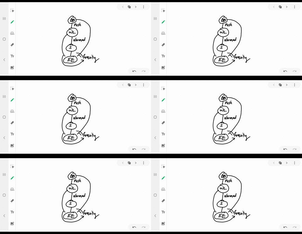
Solved Describe A Situation For Each A Draw An Interaction Diagram Following The Steps Of Tactics Box 7 1 B Identify The System On Your Interaction Diagram C Draw A Free Body Diagram For Each
Chapter 5.2three examplesVery good examples of problems that look complicated at first but are really very simple.
Free body diagrams are used to show which forces are acting on a body at a particular instant in time. Arrows indicate the position, direction, and size of the force acting. The most likely forces acting on an athlete are friction, air resistance, weight and reaction forces. How to draw a free body diagram. Let's use the example of a rugby ...
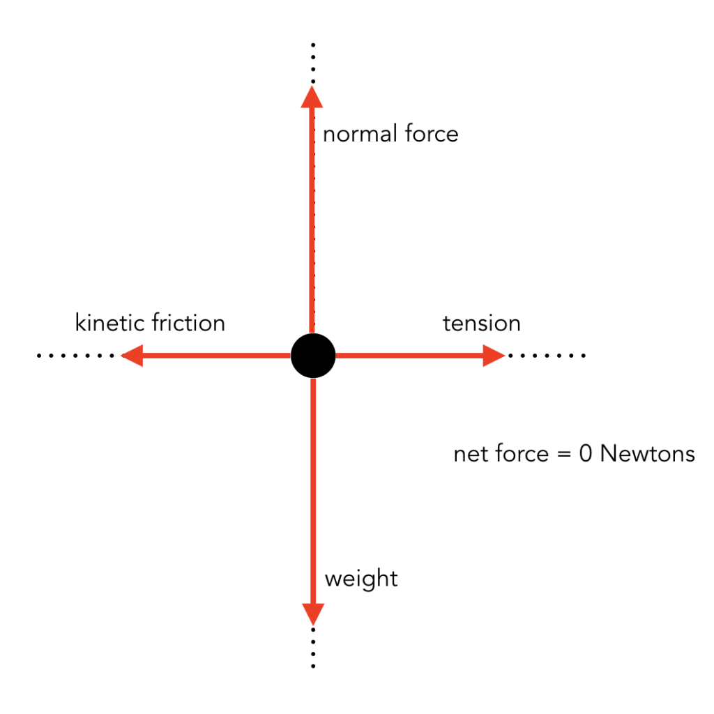
A free body diagram models the forces acting on an object. The object or 'body' is usually shown as a box or a dot. The forces are shown as thin arrows pointing away from the centre of the box or ...
Figure 5.32 (a) The free-body diagram for isolated object A. (b) The free-body diagram for isolated object B. Comparing the two drawings, we see that friction acts in the opposite direction in the two figures. Because object A experiences a force that tends to pull it to the right, friction must act to the left. Because object B experiences a component of its weight that pulls it to the left ...
Jun 10, 2018 · Given that specific weight of ethyl alcohol is 7.74 KN/m3 (Answer=FR=847KN) Figure1 Question 15 The rectangular gate CD of figure Q2 is 1.8m wide and 2m long, assuming the material of the gate to be homogenous and neglecting friction at the hinge C, determine the weight of the gate necessary to keep the gate shunt until the water level rises to ...
Free-Body Diagram 4 - 4 The first step in the static equilibrium analysis of a rigid body is identification of all forces acting on the body with a free body diagram. • Select the body to be analyzed and detach it from the ground and all other bodies and/or supports. • Include the dimensions, which will be needed
It looks like many lamps found all over the world. The three photos illustrate how the free body diagram for this structure should be conceived. The first step is to dematerialize the lamp. Identify the center of the body and draw this as a straght line. The only identifieable weight is the lamp, so this is drawn as a vector as indicated.
Examples of drawing free-body diagrams. To better understand how to draw free-body diagrams using the 3 steps, let's go through several examples. Example 1. A box is pushed up an incline with friction which makes an angle of 20 ° with the horizontal. Let's draw the free-body diagram of the box. The first step is to sketch what is happening:







(141).jpg)







0 Response to "43 draw a free-body diagram for the weight lifter."
Post a Comment