42 mallory ignition wiring diagram unilite
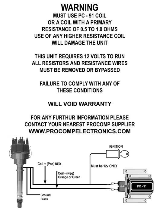
In this video Rick from Prestolite Performance / Mallory Ignition shows us how to test a Mallory Unilite Electronic Ignition Module. locate the ignition ballast resistor (or loom resistance wire). If your vehicle is not equipped with an ignition ballast resistor, install a Mallory Ignition Ballast Resistor Part No. 700 in the wire between the ignition switch and the coil (+) terminal.Failure to use an ignition ballast resistor will eventually destroy the UNILITE® Ignition ...
Mallory Ignition Wiring Diagram – mallory comp 9000 unilite breakerless ignition wiring diagram, mallory electronic ignition wiring diagram, mallory hei ignition wiring diagram, Every electrical structure consists of various distinct components. Each part ought to be set and linked to other parts in particular way….

Mallory ignition wiring diagram unilite
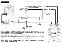
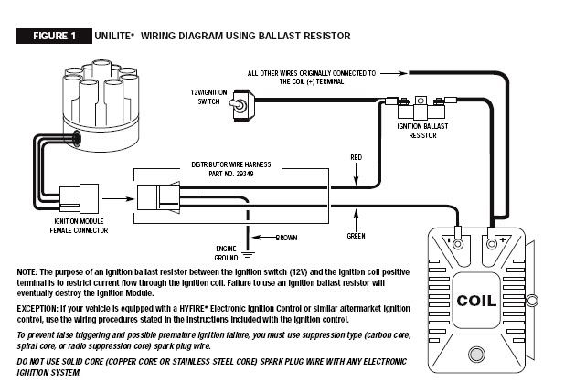
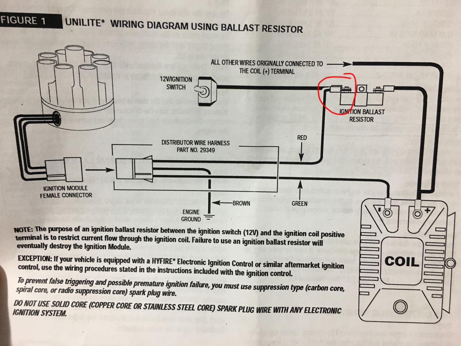
ignition wire, such as Mallory PRO SIDEWINDER ... FIGURE 1 UNILITE® WIRING DIAGRAM USING BALLAST RESISTOR NOTE: The purpose of an ignition ballast resistor between the ignition switch (12V) and the ignition coil positive terminal is to restrict current flow through the ignition coil. Failure to use an ignition ballast resistor will eventually destroy the Ignition Module. EXCEPTION: If your ... tor (or loom resistance wire). If your vehicle is not equipped with an ignition ballast resistor, install a Mallory Ignition Ballast Resistor Part No. 700 in the wire between the ignition switch and the coil (+) terminal. Failure to use an ignition ballast resistor will eventually destroy the UNILITE® Ignition Module. GENERAL INFORMATION ... Msd Ignition Wiring Diagram Diagrams Schematics With Mallory Unilite - discrd.me. discrd.me. Because you like Vehicles.
Mallory ignition wiring diagram unilite. Just simply click an image below for the correct instructions pack that would be supplied with your Mallory distributor or for just a simple wiring diagram click the . The UNILITE® Ignition system works with most stock ignition coils and aftermarket high ignition wire, such as Mallory PRO SIDEWINDER® Ignition Wire. I have a Mallory 6AL, a Mallory Promaster Classic Coil, a Mallory Unilite Distributor, and a 800CFM QuadraJet. The wiring for the Unilite requires an inline ballast so the wire for the switched 12 volt source for the distributor and the 6AL are wired directly to the stock harness coil wire that has a built in resistance. A legend returns - the tried and true Mallory Unilite Distributor line is back! The easy three wire hookup of the Unilite makes running a stock coil, a Mallory performance coil and even a Mallory HyFire CD ignition a snap. Supplied with a quality cap and rotor, the Mallory Unilite also provides a fully adjustable mechanical advance to dial in the perfect timing curve for a multitude of engine ... Location: Hendersonville Tennessee. i've got the older style mallory ignition amplifier and have already downloaded a wiring diagram to hook up to a unilite. now my question is where does the stock tach lead hook up to.does it go to the coil or to the coil hook-up on the ignition box. ------------------. 1972 chevy camaro ss 350 sbc 425 hp/356 ...
wiring diagram for mallory ing.system. Jump to Latest Follow ... The Mallory Unilite deserves every bad thing said about it. You can blow a module in a heartbeat and be dead in the water without a replacement. The added insult is the cost of the module. ... and im looking on the net for others opinions on the ignition myself . Connects to Before attempting any wiring, find which diagram illustrates your vehicle's ignition system. In the Figure 6 Wiring to a Mallory Unilite. Figure 5. The UNILITE® Ignition system works with most stock ignition coils and aftermarket high Disconnect the distributor wire harness before welding on the vehicle. Mallory Ignition Accel 35496 User Manual 8 Pages. 5462 to mallory unilite holley motor life ignition module a605 user coil 605 control accel 35496 model 6 msd distributor with question el camino ballast resistor wiring billet 7 29349 harness panhead and flathead site 690 hyfire box 3 pin diagram 3748201 1952 70 harley davidson sportster for 1936 69 electronic by a576 timers starter help the ... in the wire from the ignition switch. If you find your vehicle is not equipped with an ignition ballast resistor, install a Mallory Ignition.4 pages
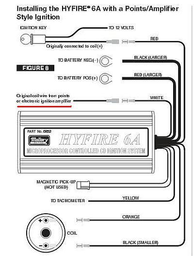
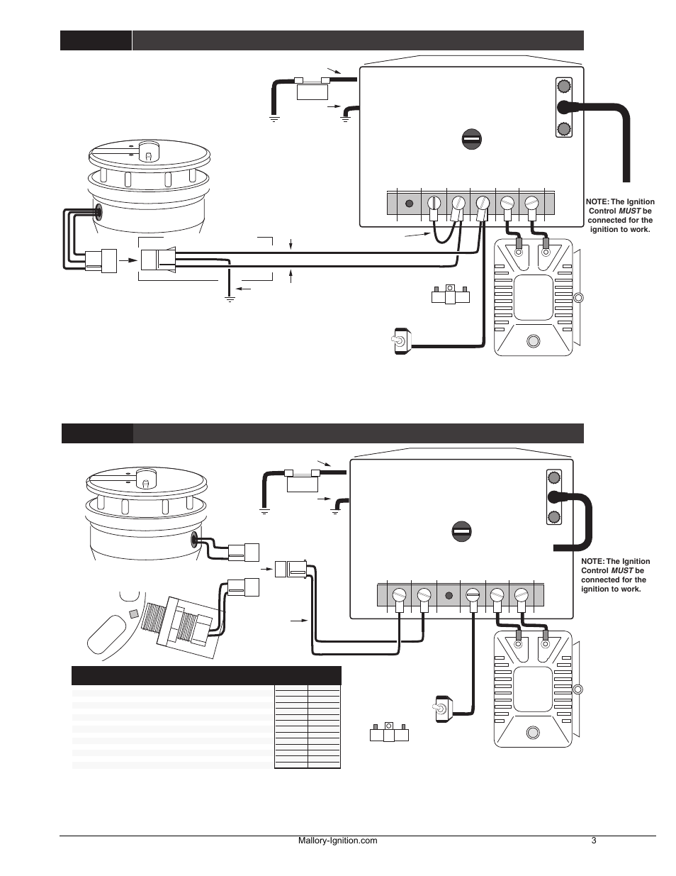
Mallory 9000 Wiring Diagram. Unilite, Distributor, Installation instructions • Read online or download PDF • Mallory Ignition Mallory UNILITE DISTRIBUTOR User Manual. spark plug wires from the original distributor cap to the UNILITE. ®. Distributor cap in the same. ground, 12 volt electrical system with a distributor. It will also work NOTE: Do not use solid core spark plug wires with the ... on Mallory Tachometer Wiring Diagram. TACH OUTPUT. WHITE. GREEN (-) That is why we have assembled the MSD Ignition Wiring Diagrams and Tech. Notes Book. . Mallory Unilite Distributor. Jacobs, Mallory, Holley, Etc.. Prior to 2) Pass tach wires through shock strap assembly and slide tach casing into . Installing and calibrating an outboard ... Step 3. Remove the. 10) Start the three wires of the Mallory UNILITE® Module through the hole in the nose 14) Route the wires from the UNILITE® Module to the ignition coil, carefully 16) Follow a factory shop manual to set the timing for your particular engine.Wiring Diagram for Mallory Distributer Don't worry if your coil doesn't look like ... Ignition Control: a points circuit (white wire) or a magnetic pickup circuit (violet and green wires). NOTE: The two circuits will never be used together. White Connects to points, electronic ignition amplifier output or to the green wire of a Mallory timing accessory.When this wire is used, the magnetic pickup connector is not used.
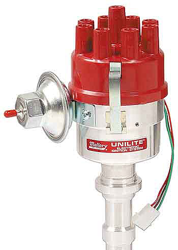
A legend has returned: the Mallory Unilite Distributor is back! A staple back in the 70's, the tried and true Mallory Unilite was the original performance distributor. Its small compact housing along with the elimination of old fashioned points made it popular among performance enthusiasts when it came to engine performance. Read More
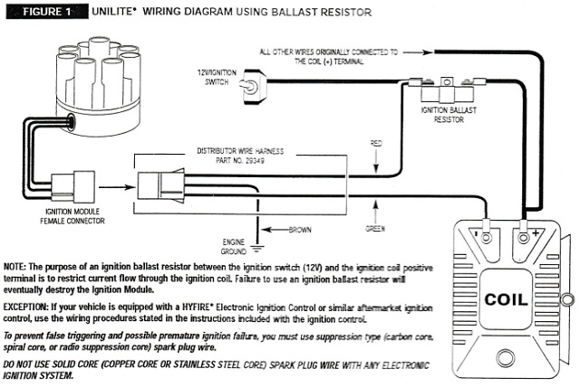
MALLORY IGNITION + COIL. UNILITE ® WIRING DIAGRAM USING BALLAST RESISTOR. FIGURE 1. NOTE: The purpose of an ignition ballast resistor between the ignition switch (12V) and the ignition coil positive. terminal is to restrict current flow through the ignition coil. Failure to use an ignition ballast resistor will
Mallory Ignition Wiring Diagram 75 | Manual E-Books - Mallory Ignition Wiring Diagram. Furthermore, Wiring Diagram gives you enough time body by which the assignments are to become accomplished. You'll be able to know exactly when the projects ought to be completed, that makes it easier to suit your needs to effectively manage your time.
Before installing the UNILITE Distributor, make sure that your vehicle is equipped with an ... FIGURE 1 UNILITE* WIRING DIAGRAM USING BALLAST RESISTOR.4 pages

When you hook up an msd box, it handles the coil voltage/current itself, leaving the "switch" for the msd and the unilite as the only things feeding from the ignition wire. This causes a problem, because the unilite draws ~0.02A, which when hooked up to the mallory ballast resistor (1 ohm) only drops the voltage by 0.02V.
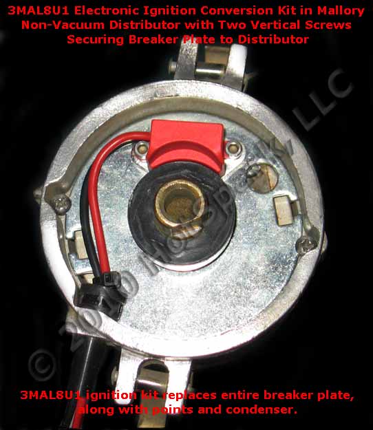
Mallory Unilite Ignition Wiring Diagram. Car Electrical Wiring Usage Porsche Distributor Wiring Diagram. Mallory Electronic Distributor Wiring Diagram Beautiful Mallory. Instructions Installing the Hot Spark Electronic Ignition. May 27, · I recently purchased a Mallory ignition for my stock 65 panhead. Does anyone know if I should run a different spark plug with an electronic ignition ...

On this website we recommend many pictures abaout Mallory Unilite Wiring Diagram that we have collected from various sites Wiring Diagram – floraoflangkawi.org, and of course what we recommend is the most excellent of picture for Mallory Unilite Wiring Diagram.If you like the picture on our website, please do not hesitate to visit again and get inspiration from our website.

From the thousands of images online concerning mallory ignition wiring diagram, picks the best collections using greatest resolution exclusively for you all, and now this photos is actually considered one of graphics collections in your greatest images gallery regarding Mallory Ignition Wiring Diagram.Lets hope you will want it. This image (Mallory Unilite Wiring Diagram throughout Mallory ...
I talked to Mallory Tech last week about this, as the notes on several of their installation diagrams conflict about damaging the module. Mallory said you can connect the red wire to either a resistance wire, the downstream side of a ballast resistor, or to full 12 volts without any damage to the module - the module is designed to operate on up to 16 volts.

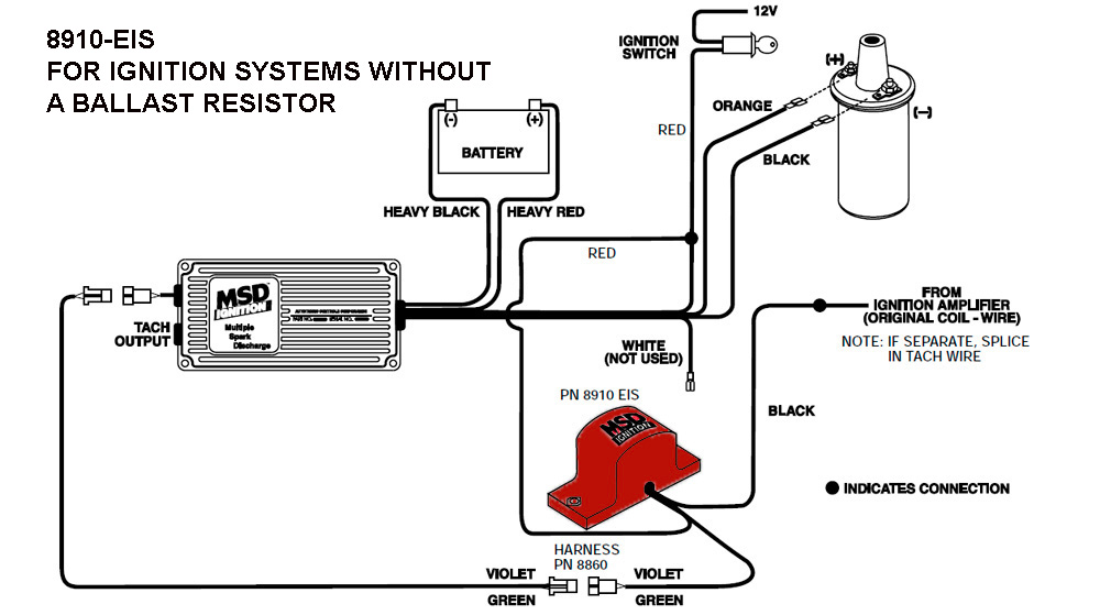
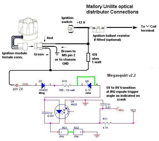
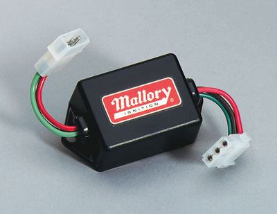
Thank you. -the unilite has 3 wires---brown, green and red. -the brown goes to ground. -the green connects to the MSD white. -the red connects to the small red of the MSD and both of these get power from the key switch----and no resistor is needed between the key and these two reds. -the MSD has an orange that connects to the coil positive ...

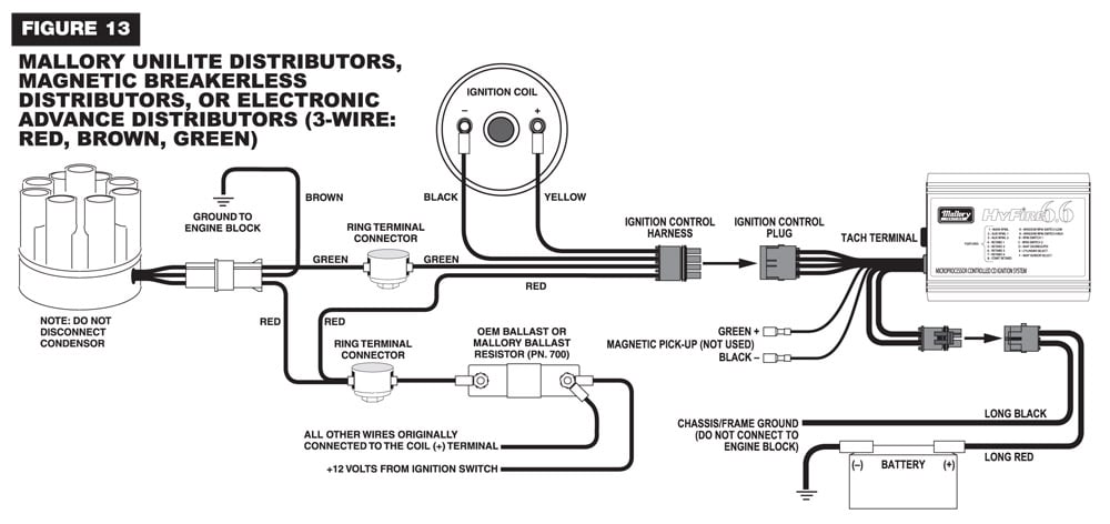
figure 1 unilite® wiring diagram using ballast resistor ignition module female connector engine ground all other wires originally connected to the coil (+) terminal distributor wire harness part no. 29349 ignition ballast resistor pn 8214 brown green red
Mallory says the red wire from the Unilite harness will also connect to that same side of the ballast resistor and that a new 12 gauge wire needs to connect the other side of the ballast resistor to the positive side of the coil. There is a second dark green wire from ignition switch position 2 that currently connects to the positive terminal ...
Unilite Wiring Diagram. Rpi engineering v8 engines 5462 to mallory unilite holley motor life australian rr forums installing a replacement distributor coil ignition user manual page 3 13 v8wizard need help no spark for bos only mopar forum and e module testing century performance center inc thesamba com bay window bus view topic fuel pump relay ...
Mallory Ignition Wiring Diagram Unilite. By Admin | December 6, 2017. 0 Comment. 5462 to mallory unilite holley motor life australian rr forums installing a replacement distributor coil ignition user manual page 3 13 rpi engineering v8 engines wiring dist directly the v8wizard question el camino central forum 4 original mode thesamba com performance transmissions view topic programmable type ...
Description: Mallory 42Series Wiring Wire Diagrams Easy Simple Detail Ideas regarding Mallory Unilite Wiring Diagram, image size 945 X 744 px, and to view image details please click the image.. Here is a picture gallery about mallory unilite wiring diagram complete with the description of the image, please find the image you need.
Whether you have the Mallory Unalite or Dual Point with or without our Power amplifier you will find below a wiring diagram to suit and also the original instructions that come with the Mallory distributors. Just simply click an image below for the correct instructions pack that would be supplied with your Mallory distributor or for just a ...
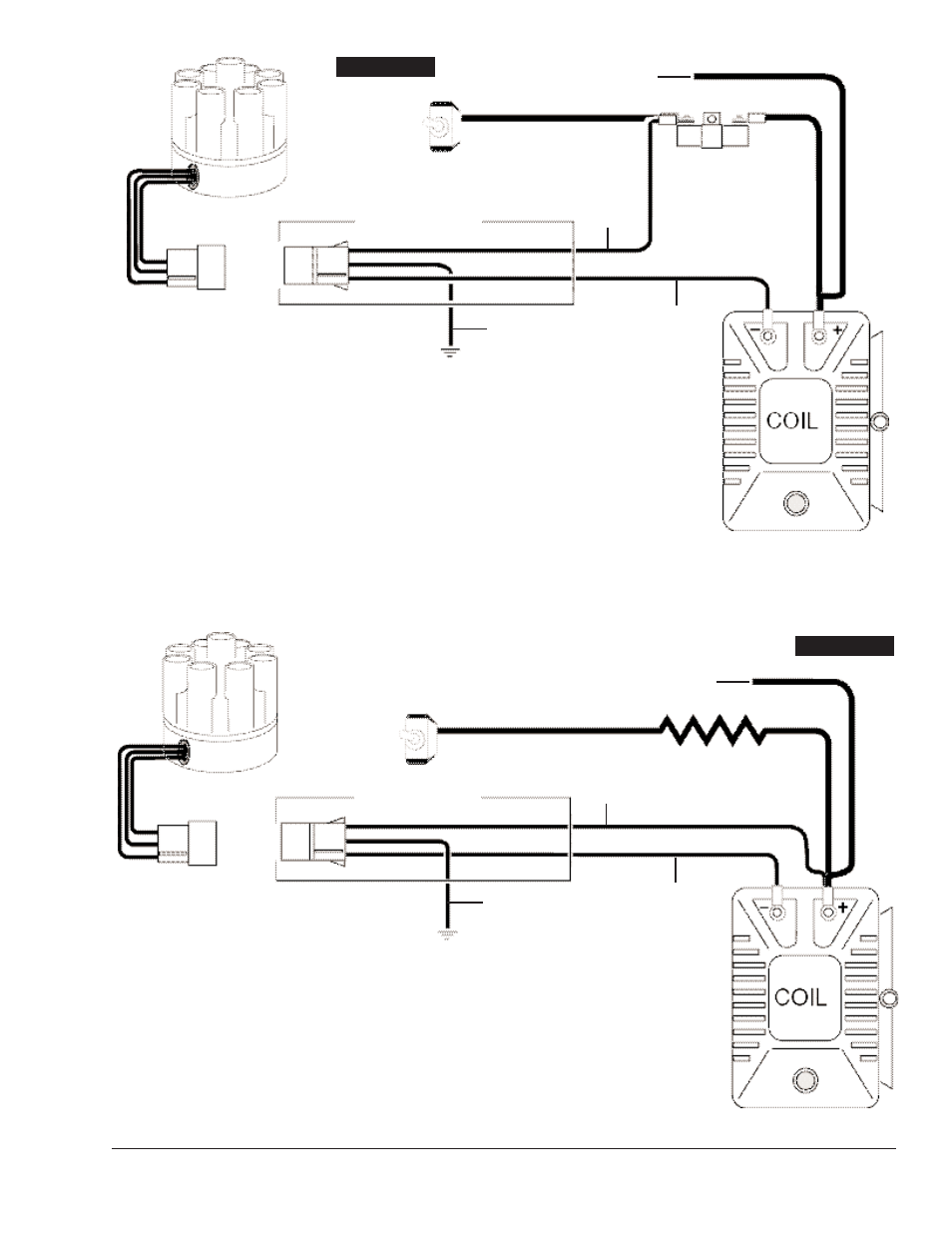
Mallory Ignition Mallory UNILITE DISTRIBUTOR User Manual • Coil • Mallory Ignition For the car. ... WIRING DIAGRAM USING OEM PRIMARY RESISTANCE WIRE.
The Mallory Unilite is sensitive to voltage spikes. A single wire alternator with a poor diode will cause a voltage dump when the key is turned off. This can send a 30 or higher volt spike through the system. As a matter of fact, a bad diode trio in a conventional alternator can do the same damage.
2 wiringall.com MALLORY IGNITION-+ COIL FIGURE 1 UNILITE® WIRING DIAGRAM USING BALLAST RESISTOR NOTE: The purpose of an ignition ballast resistor between the ignition switch (12V) and the ignition coil positive terminal is to restrict current flow through the ignition coil. Failure to use an ignition ballast resistor will.
Msd Ignition Wiring Diagram Diagrams Schematics With Mallory Unilite - discrd.me. discrd.me. Because you like Vehicles.
tor (or loom resistance wire). If your vehicle is not equipped with an ignition ballast resistor, install a Mallory Ignition Ballast Resistor Part No. 700 in the wire between the ignition switch and the coil (+) terminal. Failure to use an ignition ballast resistor will eventually destroy the UNILITE® Ignition Module. GENERAL INFORMATION ...

ignition wire, such as Mallory PRO SIDEWINDER ... FIGURE 1 UNILITE® WIRING DIAGRAM USING BALLAST RESISTOR NOTE: The purpose of an ignition ballast resistor between the ignition switch (12V) and the ignition coil positive terminal is to restrict current flow through the ignition coil. Failure to use an ignition ballast resistor will eventually destroy the Ignition Module. EXCEPTION: If your ...


0 Response to "42 mallory ignition wiring diagram unilite"
Post a Comment