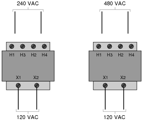
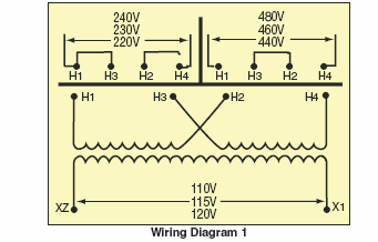
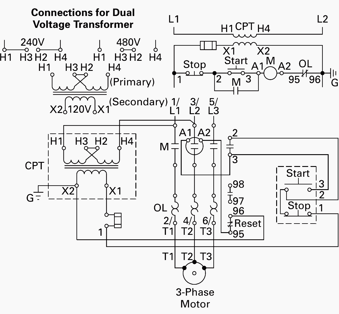
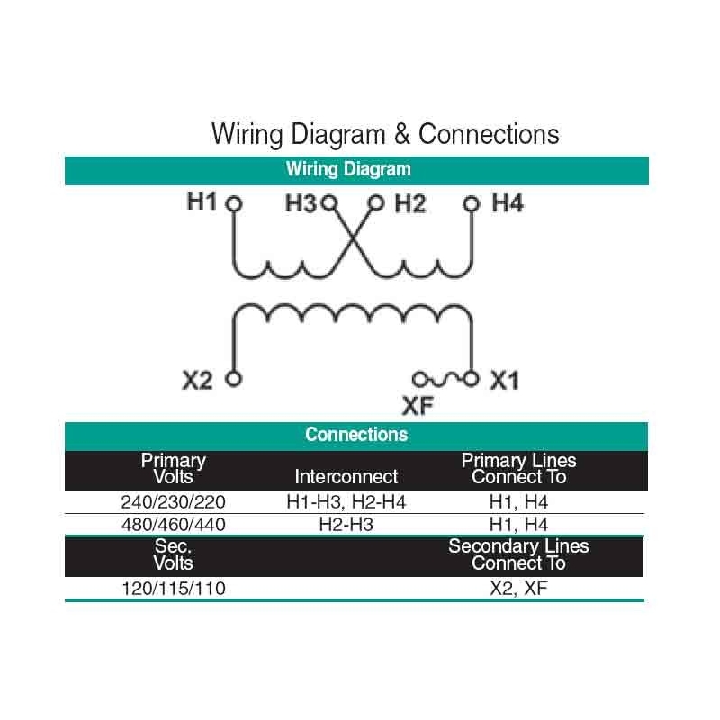
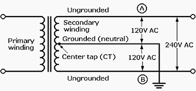
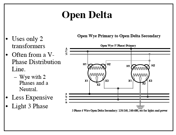
42 480v to 240v transformer wiring diagram
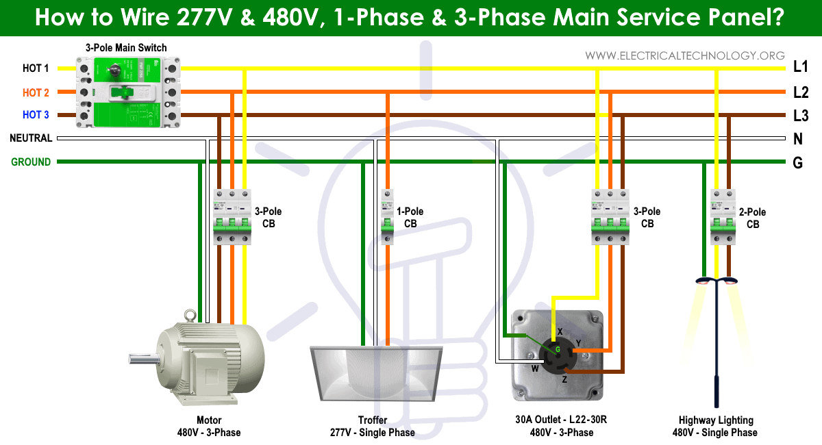
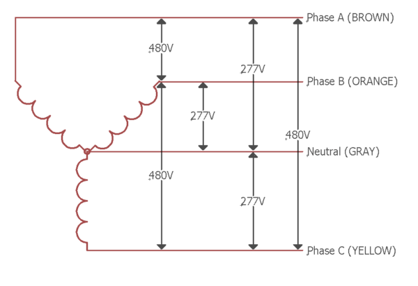
277V can also be achieved by using on site buck-boost transformer with other types of voltages such as installing an on-site (buck boost) transformer with 240V delta and 480V delta, in standard voltage system i.e. 277V can only be achieved without additional transformers in 480V-480V-480V and 277V (Wye connection). In this kind of system having both windings of T/F in Wye configuration, we ... 17.08.2007 · Wiring diagram equipment used to provide demand pulses for customer use : Sketch 47. Updated 09-19-2016. Customer wood pole - Dimensional details in accordance with American National Standards Institute (ANSI) 05.1 : Sketch 48. Updated 09-19-2016
3 phase 480 to 240 transformer wiring diagram. 3 phase 480 to 240 transformer wiring diagram ...
480v to 240v transformer wiring diagram
* The control station wiring diagram is a representation of the physical station, showing the relative positions of units, the suggested internal wiring, and connections with the starter. Symbols common to most circuits are explained on Page 5. Less common symbols are explained where they occur. NOTE - The symbols used in this publication were adapted by Allen-Bradley for use in accordance ... This book contains examples of control circuits, motor starting switches, and wiring diagrams for ac manual starters, drum switches, starters, contactors, relays, limit switches, and lighting contactors. Typical Starter Wiring Diagram — Three-Phase Separate voltages supplied by different voltage sources. How can you have two different voltages going into the same starter? One method is to run different wires from dif-ferent electrical voltage sources. You might have a 480V sup-ply that is attached to the line side of the starter, and that runs through to the motor. Another set of wires, from ...
480v to 240v transformer wiring diagram. Wiring Diagram Sheets Detail: Name: square d motor control center wiring diagram – Motor Starter Overload Wiring Diagram Save Square D Motor Starter Wiring Diagram Quotes Wire Center •. Starters are available as open . A circuit is usually composed by various components. I wanted to run a fair some of leds off of a battery to help grow a plant in an otherwise enclosed space. the load angle ... In the US, 4.5k-7.2kV from the step-down transformer wired in Delta connection via 3 Phase, 3-Wires System enters the 240V/120V distribution transformer wired in Star Connection (Two Phase, 3 Wires System). For a three phase system, the arrangement can be different for different levels of voltage. We will show the wiring diagram in the next sections of this post. Improve the efficiency of your equipment— wire these transformers to step your input voltage up or down by as much as 20%. Choose an input/output voltage combination that comes closest to matching your application, then choose the power output (in VA) of the equipment you want to operate. You probably won’t find the exact value you need; choose the next highest rating. Choose from our selection of step-down transformers, including over 150 products in a wide range of styles and sizes. In stock and ready to ship.
Typical Starter Wiring Diagram — Three-Phase Separate voltages supplied by different voltage sources. How can you have two different voltages going into the same starter? One method is to run different wires from dif-ferent electrical voltage sources. You might have a 480V sup-ply that is attached to the line side of the starter, and that runs through to the motor. Another set of wires, from ... This book contains examples of control circuits, motor starting switches, and wiring diagrams for ac manual starters, drum switches, starters, contactors, relays, limit switches, and lighting contactors. * The control station wiring diagram is a representation of the physical station, showing the relative positions of units, the suggested internal wiring, and connections with the starter. Symbols common to most circuits are explained on Page 5. Less common symbols are explained where they occur. NOTE - The symbols used in this publication were adapted by Allen-Bradley for use in accordance ...
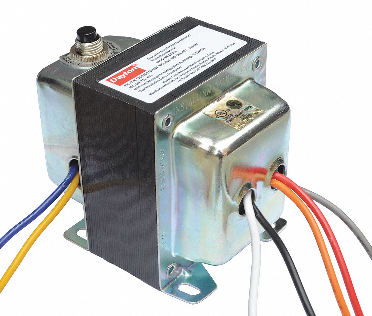
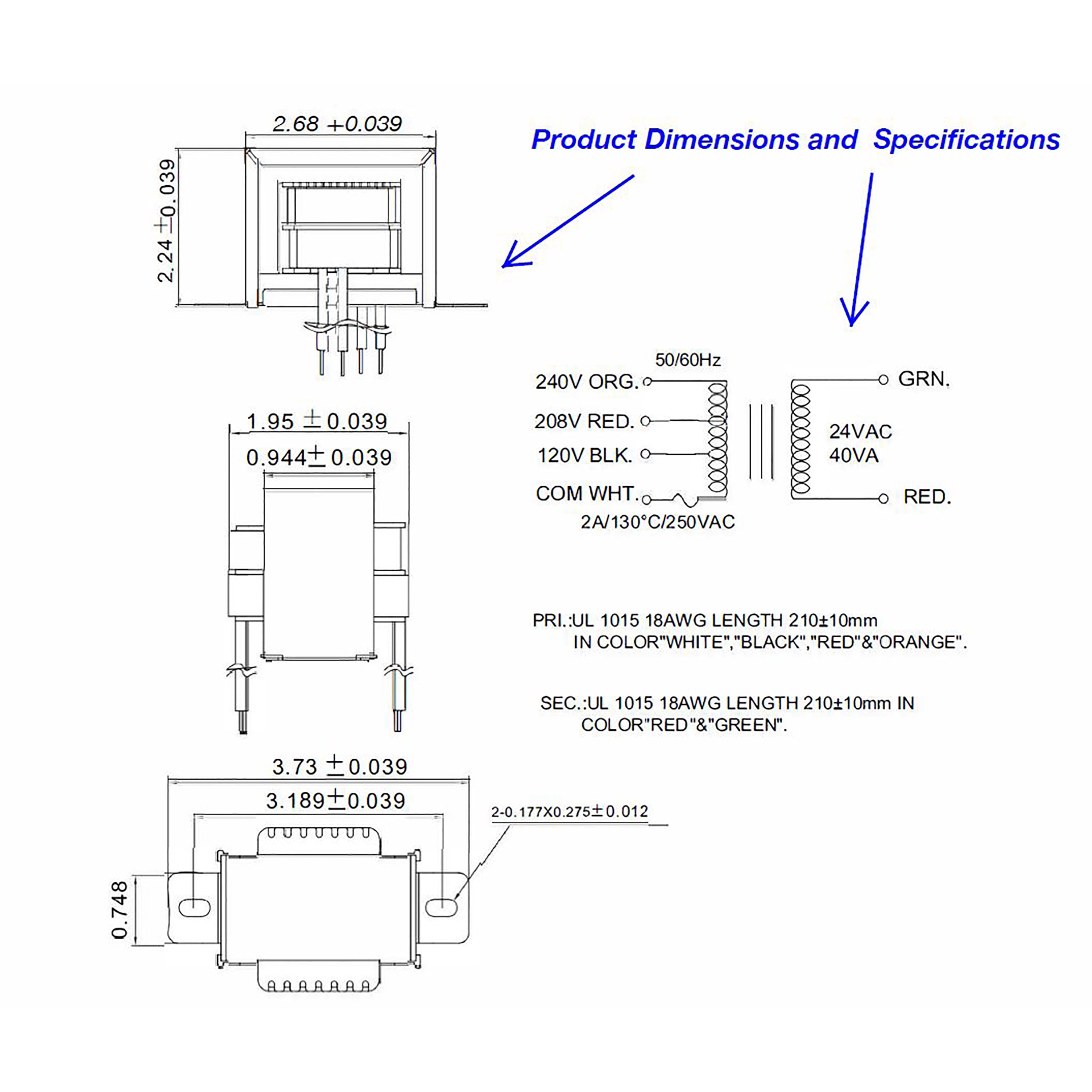
Dayton Class 2 Transformer Open 120v Ac 208v Ac 240v Ac 480v Ac Input Voltage Transformer 4vzf5 4vzf5 Grainger
Why Do The Windings Of Some Transformers Have Some Sort Of Insulation Between Each Row Instead Of Winding It All Together On Either Side Quora









0 Response to "42 480v to 240v transformer wiring diagram"
Post a Comment