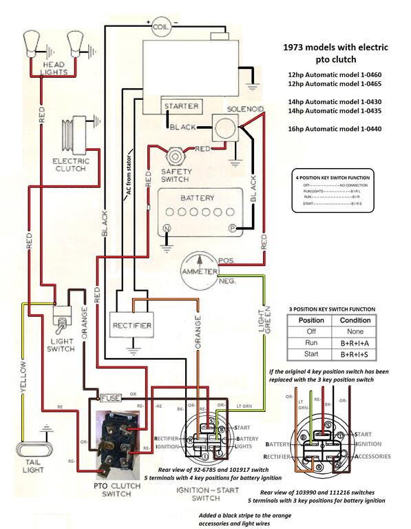
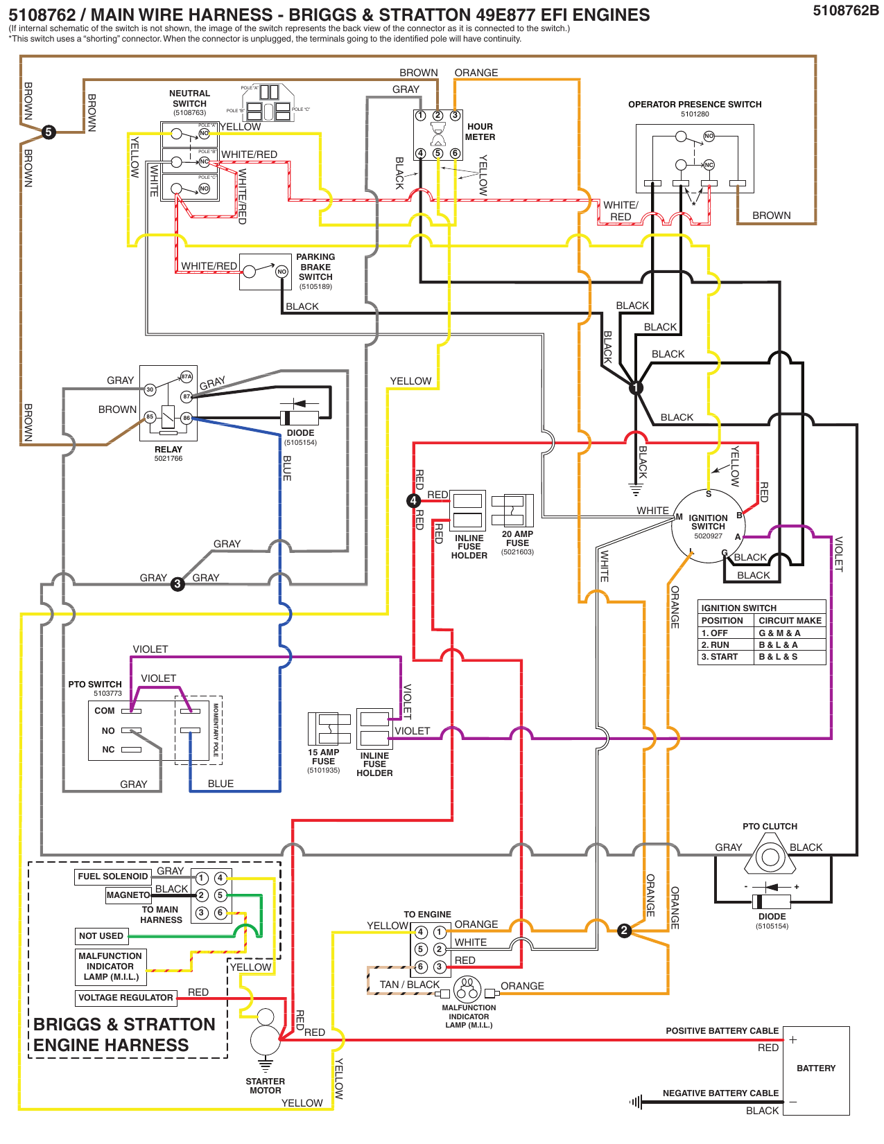
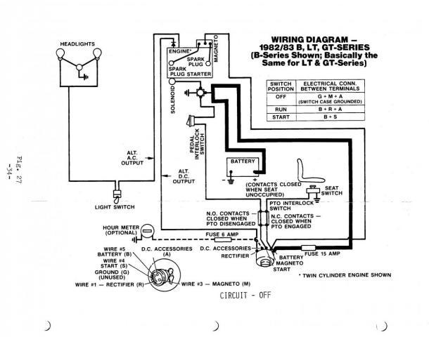
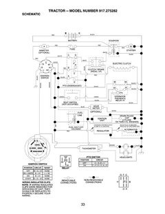
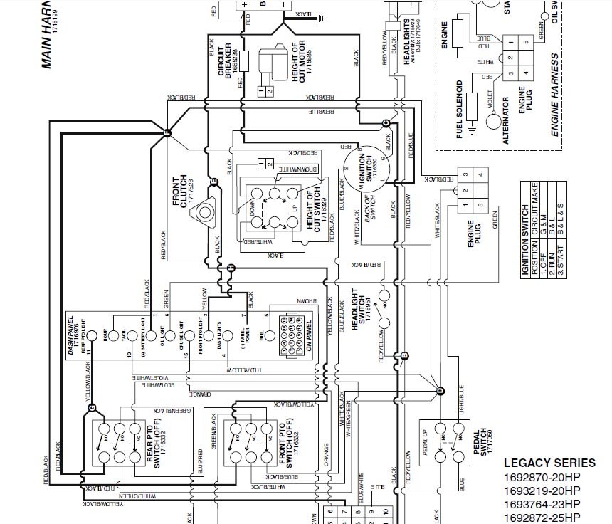
42 pto switch wiring diagram
PDF PTO INSTALLATION & OWNER'S MANUAL - Muncie Power Products the PTO operating instructions on the "Visor Label". The Visor Label 3-1/2" x 6" is to be placed on the visor on the operator's side of the vehicle (See Figure 1.2). WARNING UNDERSTaND THIS LabEL bEFORE USINg POwER TaKE-OFF (PTO) NEVER gET UNDER THIS TRUCK IF THE ENgINE IS RUNNINg! STOP PartNo.36T37507 ©MunciePowerProducts,Inc.1997 PDF PTO INSTALLATION - Muncie Power Products Place the PTO gaskets over the studs Place the PTO onto the studs and the PTO pad. Using the wiz lock nuts mount the nuts onto the step studs as shown in above. Torque to 18 ft.lb. Using the spiralock nuts install the nuts onto the 4 remaining studs. Tighten the nuts to 40 ft.lb. 3. Remove the inspection cover, as shown. 4.
Cub Cadet Pto Switch Wiring Diagram - Cadician's Blog Pto Wire Harness | Wiring Library - Cub Cadet Pto Switch Wiring Diagram Wiring Diagram contains each examples and step-by-step instructions that will allow you to definitely actually construct your project. This can be beneficial for both the individuals and for experts that are looking to find out more on how to set up a functioning atmosphere.
Pto switch wiring diagram
Kubota L3010DT/GST/HST (4wd) Parts - Messick's PTO COUNTERSHAFT [EXCEPT HST TYPE] [WITH IND-PTO] PTO SHAFT [EXCEPT HST TYPE] PTO SHAFT [HST TYPE] COOLING WATER ... To View The Parts Diagram, Please Login or Sign Up. Login. Sign Up. Or Use ... check relays, check fuel shut off solenoid, wiring connections and your key switch: answered by anonymous on 10/30/2013: Q: Why is my … Mitsubishi Fuso Fighter 6M60 Engine Fault Codes ... 9.11.2018 · External Wiring Diagram. Mitsubishi Fuso Fighter ECU External Wiring Diagram. Terminal layout. MITSUBISHI FUSO FIGHTER 6M60 Engine terminal layout. Terminal Symbol Explanation Terminals No. 1 to 34 . No. ... PTO switch: 49: SW3: Exhaust brake switch: 67: SW11: AT recognition switch: 50 ... fusesdiagram.com › chevrolet › fuse-box-diagramFuse box diagram Chevrolet Silverado 2008 EXP/PTO Fuse. 15A. Auxiliary Body Control Module (XBCM) (Export)/Power Take Off Relay (PTO) 50. AUX HVAC-IGN Fuse. 10A. Instrument Panel Cluster (IPC), Inside Rearview Mirror (ISRVM), Heated Steering Wheel Module (KA9) 51. CHMSL Fuse. 15A. Cargo Lamp/Center High Mounted Stop Lamp (CHMSL) 52. REAR DEFOG Fuse. 30A. Defogger Grid. 53. HTD MIR Fuse ...
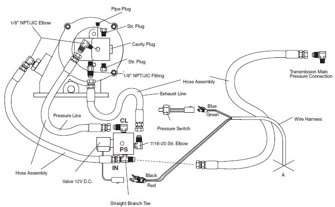
Pto switch wiring diagram. Muncie Pto Switch Wiring Diagram Muncie Pto Pressure Switch Wiring Diagram Release PTO Switch. .. Wiring Diagram: Standard "H" Shift Option Model Years Standard.Muncie Power Products is a leading manufacturer of power take-offs (PTO), hydraulic components such as pumps, motors, cylinders, valves and reservoirs, and snow & ice removal products. PDF For All 6-bolt and 8-bolt Mount Series Ptos UNDERSTAND THIS LABEL BEFORE USING POWER TAKE-OFF (PTO). Refer to Owner's Manual in glove box or on the internet at: HOW TO USE THE POWER TAKE-OFF (PTO) STATIONARY APPLICATIONS: CHOCK WHEELS BEFORE ENGAGING PTO. Manual Shift PTOs (including Air Shift) Manual Transmissions 1. Push in clutch pedal. 2. Shift transmission into ... Cub Cadet Pto Switch Wiring Diagram - Wiring Diagram Pto Wire Harness | Wiring Library - Cub Cadet Pto Switch Wiring Diagram Wiring Diagram contains each examples and step-by-step instructions that will allow you to definitely actually construct your project. This can be beneficial for both the individuals and for experts that are looking to find out more on how to set up a functioning atmosphere. ricardolevinsmorales.com › jayco-trailer-wiringJayco Trailer Wiring Diagram - Free Wiring Diagram Apr 04, 2019 · Variety of jayco trailer wiring diagram. A wiring diagram is a streamlined standard pictorial depiction of an electrical circuit. It shows the elements of the circuit as streamlined shapes, and the power as well as signal connections in between the devices.
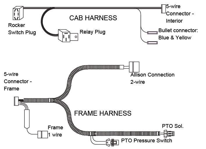
Chevrolet Silverado, GMC Sierra (2003-2006) Fuse Diagram ... Fuse box diagram (fuse layout), location and assignment of fuses and relays Chevrolet Silverado and GMC Sierra 1500, 2500, 3500 (2003-2006). PDF FR6* & FR3C PTO SERIES - Muncie Power Products B. Locate the wiring harness provided with your FR6*/3C PTO. Separate the harness at the 4-wire connector. C. The engine compartment section has the connection to the PTO activation solenoid and pressure switch. Make the connection to both components. D. Feed the 4-wire connector (white) thru to the inside of cab. Use a pass-through or drill a ⅝" › relays › relaydiagram8Convert a Negative Output to a Positive Output Relay Wiring ... May 04, 2020 · Convert a Negative Output to a Positive Output Relay Wiring Diagram: If you have a switch or an alarm or keyless entry that has a negative output that you wish to use to switch a device that requires 12V+ such as a horn, dome light, parking lights, head lights, hatch release, etc., wire a relay as shown below to convert the negative output (trigger) to a positive output. How to test electric pto switches for mowers - YouTube In this video you'll learn how an electric pto switch works and how to test them. These switches come on your riding mowers with electric clutches, as well a...
John Deere Stx38 Pto Switch Wiring Diagram Looking at the diagram from John Deere, It looks like the wiring plugs in with three (3) connectors. The PTO Switch is #17 and the Plugs are #2. John Deere Lawn Mowers If you have a wiring diagram that show the wiring of the PTO then maybe I can trace it back and see where the grounds are set up at.Top Rated Plus. WIRING DIAGRAM INDEX - Volvo Trucks wiring diagram index name description page aa power distribution frc ... illum_opt misc_switch optional_illumination mcabs ... overlay_acc mcaf main_cab aux_fan mcbbm main_cab pto mcdiag main_cab diagnostics mcdl main_cab ... Power Take-Off Switches (PTO) | Electronic Switches ... 6205-131C. Universal. 1.4" Diameter. Yellow. Yes. Basic PTO. Delta's standard unsealed PTO switches control switching for two independent circuits. This rugged and ergonomic design is a simple and cost-effective snap-in installation. They are fully customizable by knob/knob colors and graphics offerings. PDF FA6B - Muncie Power Products installation or operation of pto and driven equipment including these warnings and operator's instructions in section 3! • always disengage the pto when the driven equipment is not in operation • do not attempt to install or service any power take-off with the truck engine running. put ignition keys in your pocket before getting under truck.
Pto Switch Wiring Diagram Sample - Wiring Diagram Sample DOWNLOAD. Wiring Diagram Sheets Detail: Name: pto switch wiring diagram - 3 Speed Switch Wiring Diagram Unique Pto Switch Wiring Diagram 45 Impressive 3 Speed Switch. File Type: JPG. Source: bestcartierlovebracelet.com. Size: 64.26 KB. Dimension: 1004 x 698. DOWNLOAD. Wiring Diagram Images Detail:
Craftsman Pto Switch Wiring Diagram Sample - Wiring ... Dimension: 214 x 300. DOWNLOAD. Wiring Diagram Images Detail: Name: craftsman pto switch wiring diagram - Craftsman Riding Mower Electrical Diagram Wiring Within Lawn Ignition Switch. File Type: JPG. Source: originalstylophone.com. Size: 237.52 KB.
› - › mediaWIRING DIAGRAM INDEX - Mack Trucks wiring diagram − type om w/obd 2013 eng product schematics 22437775 04 1 (2) 1 (52) wiring diagram index name description page aa power distribution 1/2 3 ab power distribution 2/2 4 ac key sw., start & charning 5 ad grounding 6 ba vehicle ecu 1/4 7 bb vehicle ecu 2/4 8 bc vehicle ecu 3/4 - dcl connector 9
PDF ECM not seeing PTO On signal - National Highway Traffic ... Having a hard time locating a diagram of the PTO switch input to the ECM connector. Any help would be greatly appreciated. Trey Regar 21 posts since Feb 3, 2015 Re: ECM not seeing PTO On signal Oct 20, 2020 6:59 PM it shows a remote pto accelerator and pto switch on the cummins wiring diagram per your serial number. is that what your looking for?
› - › mediaWIRING DIAGRAM INDEX - Mack Trucks power distribution frc 1/2 wiring diagram: aa spf44a spx03ea3 fb2a1-0.8 ag:0 b a17.b:2 ai:4 c frc_j3:c5 aq:1 b mcsc:a9 f61a1-0.8 hb:2 d a131b.a:4 f15a1-5.0 bi:3 c x210a.a:d f87 15a cust. a b f71 15a center pin hot a b f60 30a hvac fan a b f61 5a lvd sens/ vendor ttu a b f76 30a 3968162 a f05 30a lecm4 b f06 20a rh sleeper pwr ports/ console b ...
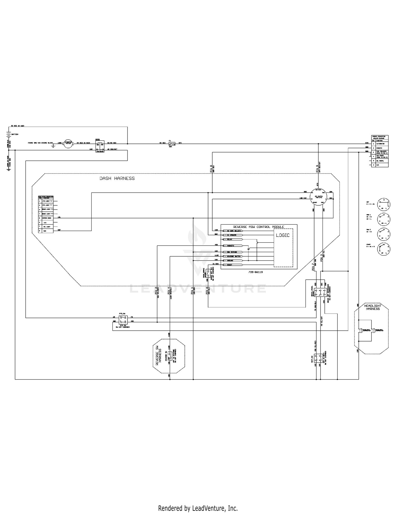
John Deere L130 Pto Wiring Diagram The electric PTO clutch on a John Deere L runs a volt system and controls Plug the connector from the wiring harness into the right side of the clutch. john deere L lawn tractor wiring diagram for safety switches Hope this helps some. L John Deere PTO problems I was mowing and deck stopped. My JD L just experienced the infamous PTO anti ...
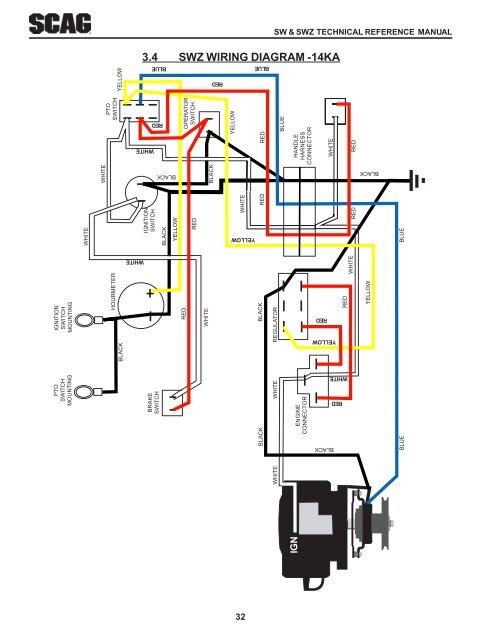
Pto Switch Wiring Diagram - easywiring The green wire in back of connector is up. Variety of pto switch wiring diagram. Route the 3 wire plug down to the pto and connect to the solenoid 3 wire plug. Wiring diagram consists of numerous detailed illustrations that display the link of assorted items. Variety of pto switch wiring diagram.
Pto Switch Wiring Diagram - Wirings Diagram Took - Pto Switch Wiring Diagram The diagram provides visual representation of an electrical structure. On the other hand, this diagram is a simplified variant of the arrangement. It makes the procedure for assembling circuit easier. This diagram provides advice of circuit components as well as their own placements.
PDF Pto Installation and Operator'S Manual wiring diagram. The green wire in back of connector is up. Connect the power wire to a 12V keyed accessory power source. Modification of wire harness is NOT recommended. Notify Customer Service if modifications are required. 7. Route the 3-wire plug down to the PTO and connect to the solenoid 3-wire plug. Be sure to route away from moving ...
Pto Switch Wiring Diagram - Cadician's Blog - Cadillac Took - Pto Switch Wiring Diagram Wiring Diagram includes numerous comprehensive illustrations that present the link of assorted products. It includes directions and diagrams for different kinds of wiring techniques and other products like lights, windows, and so forth.
› cgi-bin › viewitWiring diagram for 550 Oliver - Yesterday's Tractors Re: Wiring diagram for 550 Oliver in reply to scootergmc, 02-03-2022 13:37:45 Thank you again for sending me the diagrams for my gas 550 oliver I sent you a couple pictures I dont know where all those wires connect you even on the diagram could you help me out a little or should I just go fart thank you for your help Jack by the way I am going ...
X500 John Deere Pto Switch Wiring Diagram - schematron.org Type into google john deere riding mower wiring diagram for pto. Most John Deere lawn mowers are equipped with an electric PTO (Power Take Off). The electric clutch is operated by a switch located on the dashboard of the Remove the wire harness connector, place the flat head screw driver under the . Chris, first try to adjust the clutch.
fusesdiagram.com › chevrolet › fuse-box-diagramFuse box diagram Chevrolet Silverado 2008 EXP/PTO Fuse. 15A. Auxiliary Body Control Module (XBCM) (Export)/Power Take Off Relay (PTO) 50. AUX HVAC-IGN Fuse. 10A. Instrument Panel Cluster (IPC), Inside Rearview Mirror (ISRVM), Heated Steering Wheel Module (KA9) 51. CHMSL Fuse. 15A. Cargo Lamp/Center High Mounted Stop Lamp (CHMSL) 52. REAR DEFOG Fuse. 30A. Defogger Grid. 53. HTD MIR Fuse ...
Mitsubishi Fuso Fighter 6M60 Engine Fault Codes ... 9.11.2018 · External Wiring Diagram. Mitsubishi Fuso Fighter ECU External Wiring Diagram. Terminal layout. MITSUBISHI FUSO FIGHTER 6M60 Engine terminal layout. Terminal Symbol Explanation Terminals No. 1 to 34 . No. ... PTO switch: 49: SW3: Exhaust brake switch: 67: SW11: AT recognition switch: 50 ...
Kubota L3010DT/GST/HST (4wd) Parts - Messick's PTO COUNTERSHAFT [EXCEPT HST TYPE] [WITH IND-PTO] PTO SHAFT [EXCEPT HST TYPE] PTO SHAFT [HST TYPE] COOLING WATER ... To View The Parts Diagram, Please Login or Sign Up. Login. Sign Up. Or Use ... check relays, check fuel shut off solenoid, wiring connections and your key switch: answered by anonymous on 10/30/2013: Q: Why is my …













0 Response to "42 pto switch wiring diagram"
Post a Comment