45 hella relay wiring diagram
How to Wire a Hella 12V Relay - It Still Runs Step 1 Strip one-half inch of insulation from each wire that will connect to the relay. Four-pin relays use four wires and five-pin relays usually use five wires. In some applications, five-pin relays omit the fifth wire. Step 2 Slide the circular end of a wire terminal over the stripped end of a wire. PDF Hella Off-Road Lights Installation Instructions Install the Hella relays (available from accessory dealers) in a splash-proof position, with the connection terminals pointing downwards. Lay the cables and connect them in accordance with circuit diagram B Connect terminal 86 of the second relay to the existing reverse light. Installation Pendant or upright installation is possible.
aej.adwokatniemyjska.pl 13-02-2022 · Horn relay. 13A821D. Free Shipping Free shipping on orders over **. This factory-correct reproduction is manufactured to the highest quality standards for use with original or reproduction steering wheel assemblies. See below for …

Hella relay wiring diagram
Hella Solid State Relay Wiring - Wiring Diagrams with ISO Flasher unit with microprocessor technology. HELLA H Solid State Ceramic 32 Amp SPST Mini Relay. by HELLA. 4-way mini relay box kit Conveniently packaged HELLA quality and performance. 5 PACK 40/30 AMP Waterproof Relay and Harness - Heavy Duty 12 AWG Wiring Harness - 12V DC 5-PIN SPDT Bosch Style Automotive Relay. How To Wire Fog And Driving Lights Harness Wiring Diagram Harness Wiring. Note: This is a general wiring diagram for automotive applications. Use as reference only. Your lamp kit harness my have different wire colors. Locate the low beam or high beam light lead on one headlamp by using a circuit tester. RELAYS PRODUCTS AND APPLICATIONS - Hella Hella relays - development progress 1960 A-relay with metal housing. 1965 E-relay: control relay for flasher unit. 1968 L-relay: first modular system. 1970 Bi-stable relay for switching between low beam and high beam. 1972 Q-relay with plastic base plate, also available with built-in fuse. 1973 V-relay: PCB relay for automatic placement. 1976
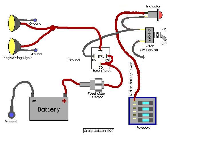
Hella relay wiring diagram. Hella Driving Light Wiring Diagram - schematron.org Hella Driving Light Wiring Diagram. Driving lights and fog lights came about as car owners navigated the Pictured is my wiring diagram for installing two fog lights with fuses. The use of a Hella relay as supplied with driving and fog lamp kits, when fitted and wired as shown in the wiring diagrams (see over), eliminates voltage loss to . PDF INSTRUCTION SHEET Wiring Kit Part No. 5224 - Hella The use of a Hella relay as supplied with driving and fog lamp kits, when fi tted and wired as shown in the wiring diagrams (see over), eliminates voltage loss to the lamps, ensures maximum light output and prevents overloading of the vehicle's wiring and switches. Triangular Distributed Load Shear And Moment Diagram 16-01-2019 · Wiring Diagram Pictures 16.01.2019 16.01.2019 6 Comments on Triangular Distributed Load Shear And Moment Diagram The first part of being able to calculate a beam problem is to be able to calculate the shear and moment diagrams, and the equations that represent these. Wiring | HELLA Quicklink 24V. Very flexible connector system that can be integrated in EasyConn or Superseal systems. Connection to any point on the flat cable - free positioning. User-definable expansion possible. Download, PDF (1.00 MB) 12 V cabling. Modular design. Easy and process-reliable installation.
Laki-laki Ini Berupaya Setubuhi Tetangga Usai Mengintip Mandi 14-02-2022 · Jeprianor bersama Budi Febian (DPO) berupaya menyetubuhi DL alias DW (23) usai mengintip korban mandi di barak yang ditempatanya tersebut. How To Wire Driving/Fog Lights - Moss Motoring This wiring diagram will stay with the car so make it neat and easily readable. Pictured is my wiring diagram for installing two fog lights with fuses, a switch, and a relay. If you need assistance drawing a diagram, refer to your car’s factory workshop manual (reprints are … How To Wire Hella 500's The Right Way - Tacoma World Run a wire from the second pin on the switch to the 85 pin on the relay. Use a female type spade connector at the end to connect to the relay. Now for the 3rd wire. This wire goes to the ac controls. Pop the ac control assembly out of the dash using a utility knife, but be careful not to break the blade. Relays | HELLA HELLA offers a wide range of relays for different applications. The electro-mechanical plug-in-relay has been one of HELLA's core products for many years. As switch amplifiers used to control electrical loads in plug-in standard models, these electronic components can be controlled by control units. HELLA relays feature diodes or resistors to ...
6.0 Powerstroke Oil System Diagram - Wiring Diagrams Free 10-12-2018 · We expect this 6 0 powerstroke wiring diagram pic will provide you with some more point for your need and we hope you enjoy it. You can also find other images like wiring diagram, parts diagram, replacement parts, electrical diagram, repair manuals, engine diagram, engine scheme, wiring harness, powerstrke box, vacuum diagram, timing belt, timing chain, … A Better Way To Create A Latch With Disarm Wire? 12-02-2022 · A Better Way To Create A Latch With Disarm Wire? - Hello. I'm working on a project vehicle that has pocket door handles, similar to c6/c7 corvettes. I sourced some liftgate handle switches to trigger the door release actuators. Also using a Digital Guard Dawg iKey Premier for rfid proximity arming/d Relays, Horns and Switches Hella Electrics: Diagram. Technical Data. Notes. Cross Reference. Description. Part No. Relays. 10. Heavy Duty. 003437101 - Single - Min Order Qty: 1. Nominal Voltage.100 pages Amazon.com: 12V Auto Waterproof Fuse Relay Box Block [6 ... Buy 12V Auto Waterproof Fuse Relay Box Block [6 Bosch Style Relay Holder] [6 ATC/ATO Fuse Holder] Universal Relay Block Box for 12V Automotive Vehicles Cars Marine Boat Light Equipment: Fuse Holders - Amazon.com FREE DELIVERY possible on eligible purchases
Hella HL87424 Mini Relay, 12V 10/20A , SPDT with Diode, High ...
Hella 4ra Relay Wiring Diagram Wire Diagram Symbols. simple relay switch wiring - could you advise with the wiring of a relay (hella 4ra ) as the technicals explain, but skip over the switch placement. Can you tell me simply the configuration to wire a relay, especially how a switch is wired to the relay, I think with the option to place bef.Hella Supertone Horns [Archive ...
Help Installing Hella FF 75 fog lights - JK-Forum.com - The ...
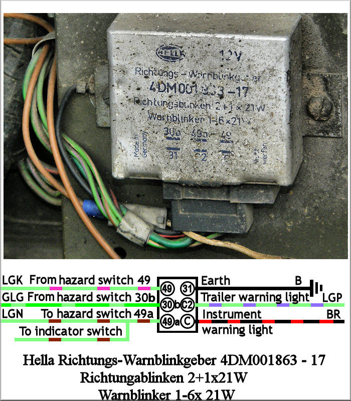
RELAYS AND RELAY DEVICES PRODUCTS AND ... - Hella Due to the complexity of wiring, they are less common. Page 44. 44 | FLASHER UNITS. Flasher Unit 6 V / 12 V, with ...84 pages

Hella Horn Wiring Harness 02-14 WRX, 04-14 STI
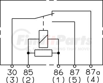
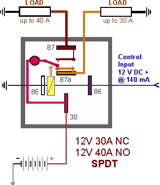
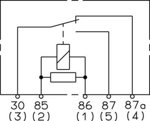
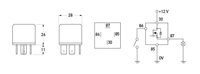
OPTIMUM PERFORMANCE RELAYS & FLASHER UNITS Diagram indicating wiring/current flow for HELLA B1910 (Disc horn set) or B7424 (Trumpet horn set). HELLA 4Pin Relay (N/O) C4003 (12V) | C4002 (24V) Terminal configuration 30) Output 85) Coil trigger (-) 86) Coil trigger (+) 87) Battery (+) HELLA AUTOMOTIVE RELAYS S1 30 (3) 85 (2) 86 (1) 87 30 85 86 87 (5) A FUSE
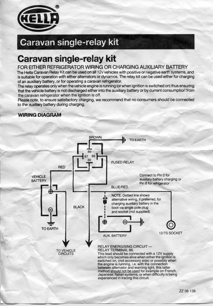
TheSamba.com :: Gallery - Caravan single-relay kit Hella 4RA ...
Hella 4ra Relay Wiring Diagram - schematron.org Relays have been used to remotely control circuits for over years. The technology .. 4RA Mounting instructions. Hella Rallye Compact Series 4. Switch 6EH 5. Relay 12 V 4RA 24V 4 RA 6. Hella wiring . The Hella solid state relay offers faster switching speeds than a standard mechanical solenoids and the Hella relay is well suited to adjacent ...
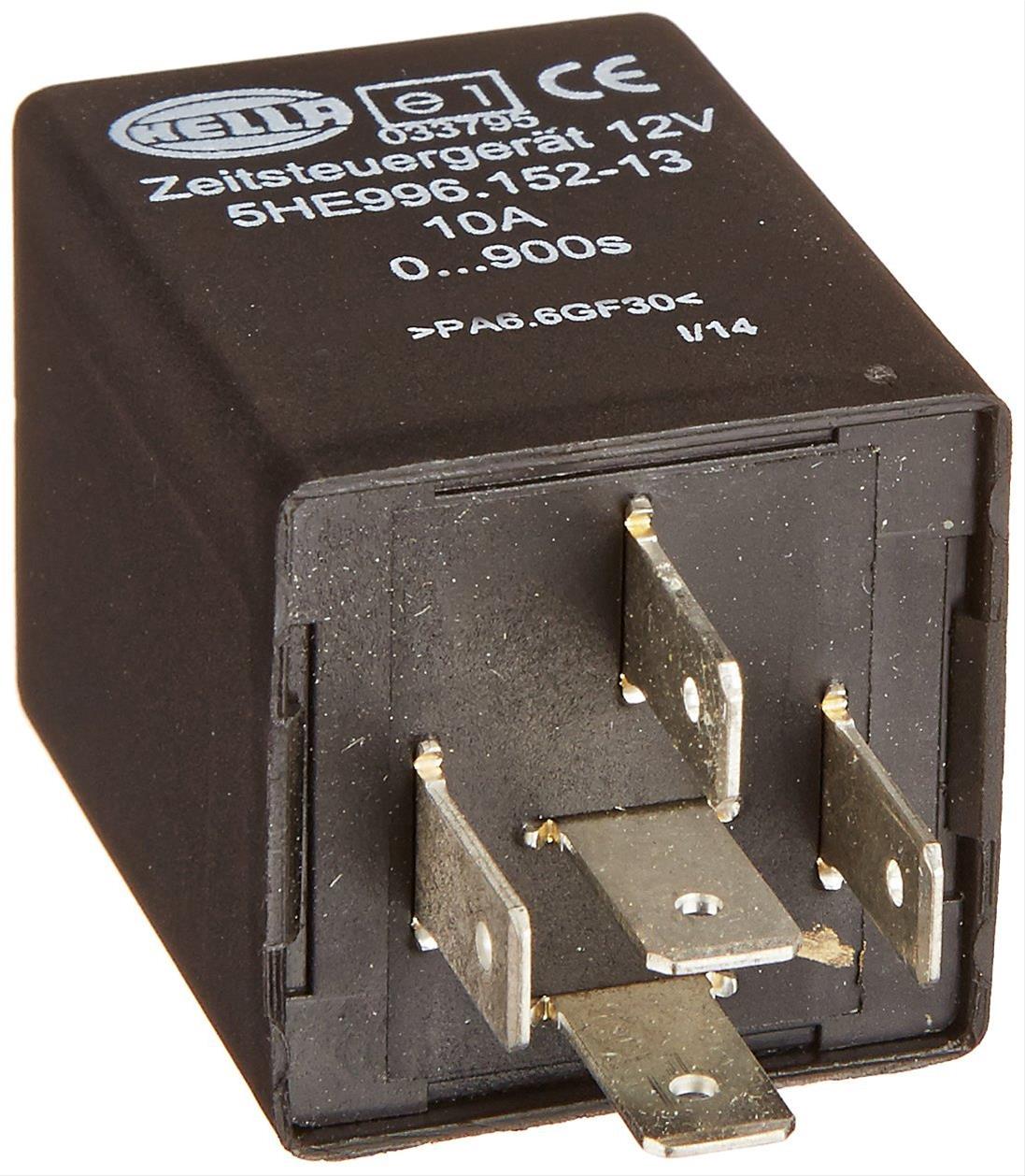
Hella 996152131 Hella Adjustable Time Delay Units | Summit Racing
Hella Driving Light Wiring Diagram Hella Ultimate Style/Black Magic Driving Lamp System. INSTALLATION (1) Complete wiring system with 12V/30A relay, in- 4 for diagram of wiring.This wiring diagram will stay with the car so make it neat and easily readable. Pictured is my wiring diagram for installing two fog lights with fuses, a switch, and a relay.
Relays, Horns and Switches Hella Electrics:
Hella Horn Relay Wiring Diagram - U Wiring Hella Horn Relay Wiring Diagram. 2 Way Rocker Switch Wiring Diagram Motorcycle Wiring Trailer Light Wiring Light Switch Wiring. 12 Came Electric Gates Wiring Diagram Electrical Wiring Diagram Motorcycle Wiring Electric Gates. Diagram Ham Radio Page Industrial Latching Relay Wiring 5 Pin Nissan Xterra Automotive Electrical Jeep.
931410057 by HELLA USA - Wiring Relay
Hella horn relay wiring help/diagram ? | IH8MUD Forum Hella horn relay wiring help/diagram ? Thread starter SoCal_80; Start date Oct 8, 2015; Watchers 8 1; 2; Next. 1 of 2 Go to page. Go. Next Last. SoCal_80. Joined Apr 21, 2008 Messages 1,486 Location So Cal. Oct 8, 2015 #1 I did my checking however cannot find a thread or diagram that shows how to wire in an aftermarket horn, in this dual Hellas ...
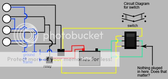
Spotlight relay connecting up
RELAYS AND RELAY DEVICES PRODUCTS AND ... - Hella | 4 5 1951 First hot-wire flasher unit 1960 A-relay with metal housing. Mechanical threshold voltage controller for windshield wipers 1965 E-relay: the first fully electronic flasher unit 1968 L-relay: the first modular system 1969 Wipe/wash interval control unit 1970 K-relay: current controlled relay for direction indicator lamps Bi-stable relay for switching between low and high beam
Need Help with Solid State Relay wiring - Camaro5 Chevy ...
The ultimate headlight upgrade H4 (not LED or HID ... 24-03-2021 · The harness is entirely plug and play, the factory switch will control the relay on the harness, to control the lights as if it were stock. ... These harnesses are made in the USA by RallyLights using 12 gauge wiring and Hella components. Rallylights part number HL28200. ... Link to the headlight wiring diagram Here.

Hupen Signalhorn Supertone Horn Kit 2 Stück in Gold (118db)
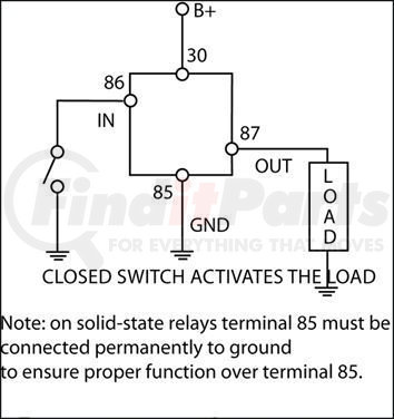
Hella Solid State Relay (PN: HELLAH41773001) solenoids and the Hella relay is well suited to these applications. • When using a solid state relay to control a device that may have significant fly-back voltage such as most solenoids, LPE recommends connecting a Transient Voltage Suppression (TVS) Diode across the device. This wiring configuration can be seen in the adjacent wiring diagram.
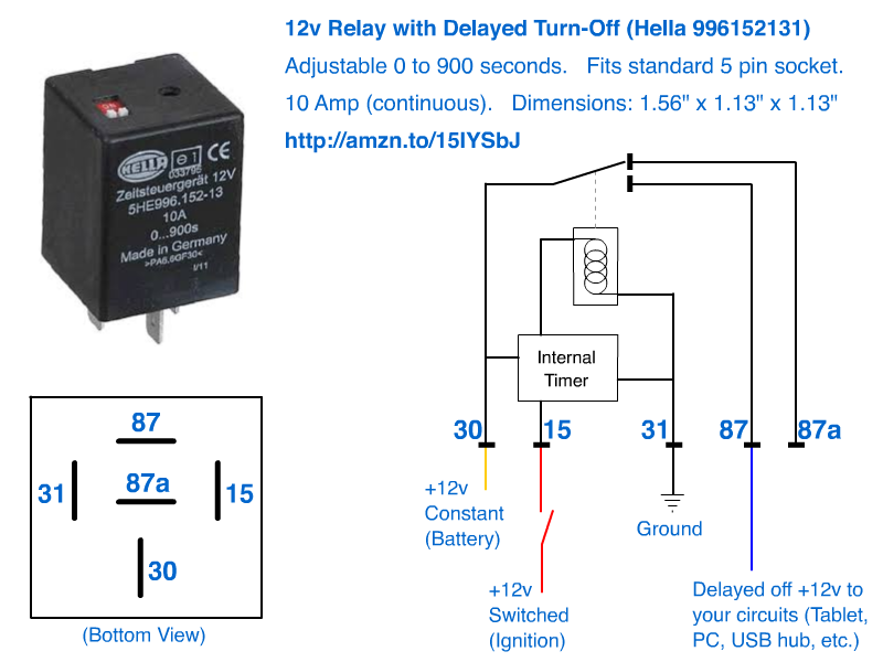
12v Delayed turn-off or turn-off (howto)
Zhejiang Meishuo Electric Technology Co.,Ltd Zhejiang Meishuo Electric Technology Co.,Ltd found in 2007,We are professional manufacturer, our main product : automotive relays, mini relays,pcb relays,power relays,latching relays,solendoid water valve , automotive connector and harness.
Hella Twin Supertone Horns | IH8MUD Forum
Hella Relay 4rd Wiring Diagram Hella Horn Relay with Wiring Harness (12V,Relay) · out of 5 stars 30 · . Received a 4RD 20A relay with no bracket. The Hella box has Wiring diagram right between the pins is perfect. Read more. OKA Relays for Automotive use - SPDT 12V 40A/30A 85 Ohm Coil. Typical Circuit. Relay Switch Circuit Diagram Hella.

12V Hella fog light headlamp relay NOS
RELAYS PRODUCTS AND APPLICATIONS - Hella Hella relays - development progress 1960 A-relay with metal housing. 1965 E-relay: control relay for flasher unit. 1968 L-relay: first modular system. 1970 Bi-stable relay for switching between low beam and high beam. 1972 Q-relay with plastic base plate, also available with built-in fuse. 1973 V-relay: PCB relay for automatic placement. 1976
HELLA 5 Point Wiring Relay For Use with Hella Horns 4RA 933 791-101
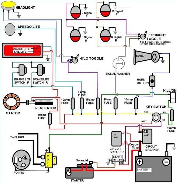
How To Wire Fog And Driving Lights Harness Wiring Diagram Harness Wiring. Note: This is a general wiring diagram for automotive applications. Use as reference only. Your lamp kit harness my have different wire colors. Locate the low beam or high beam light lead on one headlamp by using a circuit tester.

Building
Hella Solid State Relay Wiring - Wiring Diagrams with ISO Flasher unit with microprocessor technology. HELLA H Solid State Ceramic 32 Amp SPST Mini Relay. by HELLA. 4-way mini relay box kit Conveniently packaged HELLA quality and performance. 5 PACK 40/30 AMP Waterproof Relay and Harness - Heavy Duty 12 AWG Wiring Harness - 12V DC 5-PIN SPDT Bosch Style Automotive Relay.
Relay Wiring for Hella 500 lights - Jeep Cherokee Forum

5HE 996 152-131 - Time Relay
Land Rover Lightweight
Hella horn relay wiring help/diagram ? | Page 2 | IH8MUD Forum

Relais, Wisch-Wasch-Intervall 5WG 003 620-081 HELLA ohne ...
RELAY SPDT 12V 40A/30A 85 Ohm Coil

Hella 500 Wiring Diagram | Ford Explorer - Ford Ranger Forums ...
Wiring Relay Hella 931680011 for sale online | eBay

Hella HL43709 Heavy Duty 24V 60A Mini Relay, SPST, with ...
Hella 500 Lights Wiring Help | Jeep Wrangler Forum
12V 4 Pin Solid State Relay - 22A

Headlight relay wiring Q - BMW 2002 and other '02 - BMW 2002 FAQ
How to Wire a Hella 12V Relay
Relays, Horns and Switches Hella Electrics:

Relay, main current HELLA 4RA 003 437-101 - Trodo.com

Horn Wiring | Car horn, Horns, Electrical diagram

Question: New horn wiring diagram - Pelican Parts Forums
Calling all Hella Optilux owners!!! | Honda Element Owners Club

HELLA H84709001 Pig-Tail Wire Harness for Mini ISO Weatherproof Relays

Hella HL87483 Mini Relay, 12V, 40A, SPST, Dual 87 Pin | Rally ...

HELLA USA 931773987

Hella Operating Current Relay 5 Poles 12V 4RA 933 791-151 ...
Need help installing hella horns | 2016+ Honda Civic Forum ...
revlimiter.net - Low Profile Headlight Wiring
Wiring 4 Hella 500 Lights - JK-Forum.com - The top ...

5 pack OLS 12 V 60/80 Amp Schalter Relais Geschirr Set ...
Another Hella 500 install question. - NASIOC

Hella horns | Toyota FJ Cruiser Forum
931773987 by HELLA USA - Wiring Relay
Hella Fog Lamps Wiring Diagram Needed.
0 Response to "45 hella relay wiring diagram"
Post a Comment