44 dei 451m wiring diagram
There are 4 different diagrams for the 451m that I have. Delta976 Registered Joined Nov 15, 2005 437 Posts Discussion Starter · #7 · Jan 1, 2006 do you want the +12v pulses driving factory relays - ground pulses driving factory relays Directly wired reversing polarity switch circuts aftermarket actuators or mercades benz and audi (vaccum) diagram? 29.09.2018 29.09.2018 1 Comments on 451m Relay Wiring Diagram. Also included in this guide are wiring diagrams for incorporating priority door locking cles, or if an actuator is to be installed, either a M Door Lock Relay . ...
To use this alarm u must use 2 relays one for lock one for unlock if you need the wiring i can send it to you or use a 451m door lock module one will control all 4 doors again if you want i can send it i will post a copy of that here soon as well as the wiring codes for. Take the large gauge purple wire and connect it to the battery.
Dei 451m wiring diagram
View and Download Directed 451m manual online. Door Lock Interface. 451m locks pdf manual download. Hello everyone, New to this board, so please bear with me... I am looking to install recessed lighting in a bedroom. Currently, the room has a ceiling fan with a light kit which each gets their own switch on a wall. What I ultimately want to do is take a single gang switch and replace it with a dual gang switch and just run another wire to the recessed lighting. The goal is to NOT cut an additional box on the wall, nor run any additional lines to the breaker. Especially since the lights are L... Use DEI 451M relay. 2 In the top left corner in a black plug. 3 Park light - trigger w/ 910 Ω resistor. Headlight - trigger w/ 349 Ω resistor. Use relays. 4 Drvr door trigger tan, pass'er door trigger tan/white, use both wires, diode isolate each. 5 The factory alarm disarm is - trigger w/ 473 Ω resistor. MUST use relay.
Dei 451m wiring diagram. • Year 2000 • Make/Model Chevy C6500 Kodiak • Mileage 242000 • Engine size Cat 3126 V6 Turbo diesel • Transmission Type (Automatic or Manual) Allison automatic Hey everyone! So long story short, I'm troubleshooting why the reverse lights don't work on a 2000 Chevy C6500 Kodiak. I have the full service manual and I've been digging into the troubleshooting and wiring diagrams. So I've finally come to this point where it wants me to locate "S214" and gives me a general location. From ... Dec 10, 2020 · Dei 451M Wiring Diagram. To properly read a electrical wiring diagram, one provides to learn how the components in the method operate. For example , in case a module is powered up and it sends out a signal of half the voltage plus the technician does not know this, he would think he provides an issue, as he or she would expect a new 12V signal ... I’m trying to install an aftermarket speaker in the trunk but can’t figure out or find the diagram for which wire goes in the remote wire Oct 8, 2016 #2 On a 1996 diagram I have there's a six wire connector and a two wire connector for the VTS. The 2-wire connector is ground and power and the 6-wire connector has a black wire in it that goes to the center (common) terminal of a 3-terminal UP/DOWN switch. Not sure if this helps but maybe... Not open for further replies.
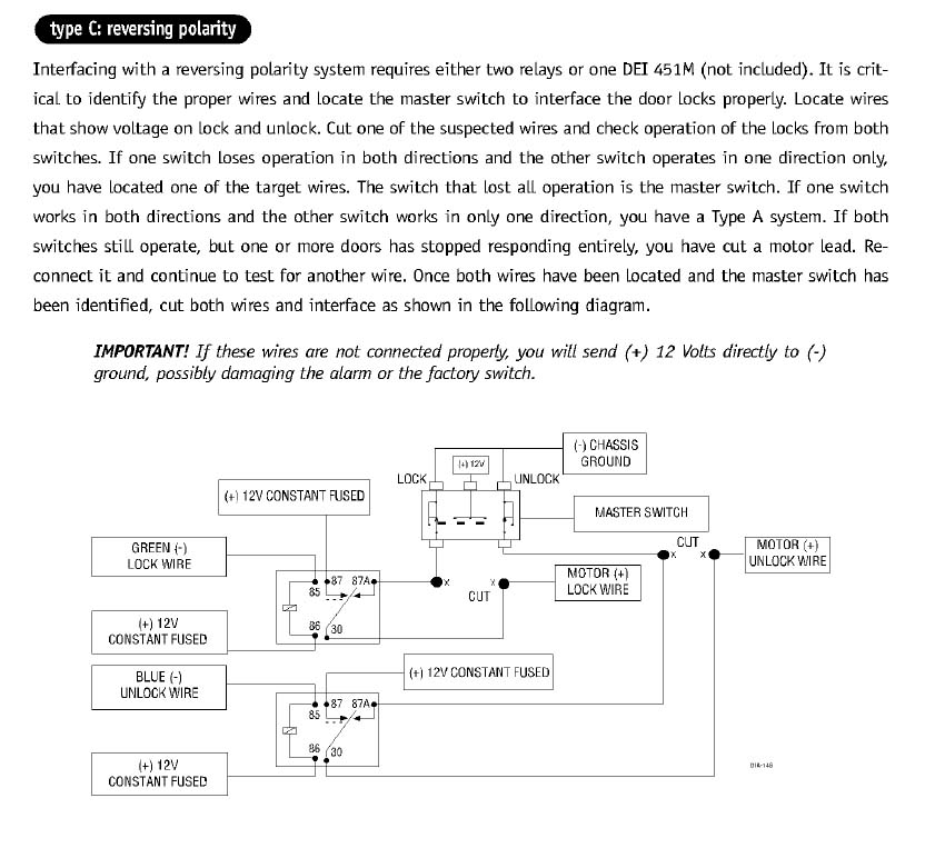
WIRING DIAGRAM C: Directly-wired reversing-polarity switch circuits. Use these instructions if the power door lock switch has four or five heavy-gauge wires. This type of switch has two outputs that rest at (-) ground. NOTE: Interfacing with these systems will require you to cut two switched leads. The 451M module must Install Essentials 451M Dooor Lock Relay Module 293 6 offers from $16.56 Universal Door Lock Relay Kit Module Triggered by Negative Pulse 22 2 offers from $14.95 Directed Install Essentials 451M Door-Lock Relay Assembly 3 2 offers from $15.98 Viper 3100V 1-Way Security System 257 7 offers from $69.00 I have searched far and low and have found bare nothing when it comes to my package car. It is a SV trim level with touch-nav & no Bose premium sound package. I am trying to figure out the correct diagram in order to solder in new speaker wires to the factory wires for a amp install. I want to keep everything as factory as possible OBV. So no fancy EQ HU 🤷♂️ How to find the starter wire with your multi meter: 1. Set to DCV or DC voltage (12V or 20V is fine). 2. Attach the (-) probe of the meter to chassis ground. 3. Probe the wire you suspect of being the starter wire. The steering column is an excellent place to find this wire.
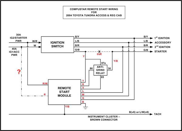
Download. DEI VIPER 560XV MANUAL PDF. Dei viper 5000 car alarms, owners guide 61 pages Summary of Contents for Viper 5901. Featuring, Viper, Hornet, Avital, Clifford Parts, Xpresskit, Autostart, Orion Cobalt, Your Valet, Python. Viper SmartStart with GPS and Viper 2-way security overview. DEI HP104 Single Channel IR Headphones HP060. 451m Relay Wiring Diagram - schematron.org Directed 451M. 4.8; 5 reviews. Door Lock Relay Module with Resistors DEI 451M ... • Includes module, wiring harness and installation guide. $9.03 Add to Cart. IN STOCK. Gallery. Directed 504KP. LED and Valet Pod for the 504K. $14.99 Add to Cart. AVAILABLE. Ships at Later Date. Gallery. 451m Relay Wiring Diagram 29.09.2018 1 Comments Also included in this guide are wiring diagrams for incorporating priority door locking cles, or if an actuator is to be installed, either a M Door Lock Relay . Anybody out there have a wiring diagram for the DEI m?? Bought one Yeah, but I have to pay retail for relays/wiring/connectors Or buy it. My next project is installing the CompuStar Remote Start (model #1W900FMS). I thought I would post the wiring installation diagram and get comments before cutting any wires. One of the 12 volt constant inputs (red wire) I still have questions about. It is the second +12 volt constant input to the remote start module as shown in the diagram below:
Keyless entry | Hyundai Forums
you need to cut your factory door lock wires and use relays to make the locks work. This is a 5 wire setup, it can be accomplished with part number dei 451m, or you can use two relays and make your own. Do a search on 5 wire door locks and you should be able to find a diagram fairly easy. C criticman Member Sep 7, 2003 723 1 16 Rome, GA
Installing Actuators
Hi guys, my 20 fuse next to the battery on the positive terminal keeps popping. It only pops when I make a left turn and the three relays next to the left side air intake move around or wiggle. I can't find the wiring diagram that list the 20 amp fuse. Do any of you guys have a link to the wiring diagram where the 20 amp fuse next to the battery on the positive terminal is listed? Please provide a link if you do have it thanks.

DEI 451M Relay installation
Directed 451M (dei-451m) Door Lock Relay Module with Resistors Page 1/2. Read Book Directed 451m Installation Guide ... 29.09.2018 29.09.2018 1 Comments on 451m Relay Wiring Diagram. Also included in this guide are wiring diagrams for incorporating priority door locking cles, or if an actuator is to be installed, either
2004 Access & Reg Cab CompuStar Remote Start Install | Toyota ...
These Directed Electronics internal door lock relays can get confusing, This wiring how to explains how these work on all Viper, Clifford, Automate and Pytho...
Factory power lock wiring to aftermarket alarm - JK-Forum.com ...
Dei 451M Wiring Diagram - New Viper Dei 451m Door ... Hayward Aqua Pod Manual - Large Pool Leaf Canister... Manual De Bienvenida - Manual De Bienvenida Calame... Yaesu Ft 736R Manual : Yaesu Ft 736r Ft 747gx Ft 8... Reliamed Blood Pressure Monitor Manual / Reliamed ... Summer Worksheets For 5Th Graders : Free 5th Grade...
DEI 451m relay question
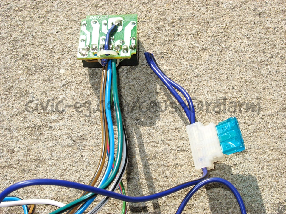
A couple of threads discuss converting the VTS relay circuit over to a DEI 451M solid state relay module. I have the relay but no schematic for the internals. Has anyone done this mod for the rear mounted, encapsulated VTS module ('95, '96, '97...)? If so, which wire colors go together?

Improve the Speed of the Fiero Electric Windows Using a 451M Micro Door Lock Relay Module
[http://www.wrxinfo.com/service\_manuals/](http://www.wrxinfo.com/service_manuals/) Been researching some torque specs for suspension stuff and was surprised about the amount of misinformation and confusion out there across forums and videos. Here ya'll go, hope this helps some of you DIYers.

Door lock Actuator wiring questions - BMW 2002 and other '02 ...
I really need to know the pinout (numbers) for the 2010 stereo harness. I have searched for about 3 1/2 hours and come up with absolutely nothing. I have a 2008 mustang that I am putting a 2010 steering wheel on, and am wiring up the controls for volume / track via a SWC module. I need to know what pins 18 and 19 are on the 2010 mustang, and which pins those would be on the 2008 mustang. any help at all would be appreciated more than you know!

VIPER DIRECTED INSTALL Essentials Micro Pre-Wired Door Lock ...
immobilizer harness wiring diagram ___ ___ ___ immobilizer harness wiring guide h2/1, h2/2, and h2/3 black immobilizer pigtail harness The starter immobilizer harness can be installed as a normally open or normally closed circuit by connecting the desired side of the three-wire immobilizer. Locate the

DIY: FC RX7 Window Switch Relay Mod PnP T-Harness - RX7Club ...
Primary Harness Diagram 8 Wire Connection Guide 9 Plug in LED and Valet®/Program Switch 11 Four-pin Shock Sensor Harness 11 Bypassing Sensor Inputs 12 Door Lock Wiring Diagrams 12-15 Transmitter/Receiver Learn Routine™ 16 Two-vehicle Operation with Single Transmitter 17 Operating-Settings Learn Routine™ 18 New Double Pulse Unlock Feature

DCI-S2000 Adapter Harness
Title: Print 2451111.DCX (6 pages) Author: Eugene@TECH3 Created Date: 10/30/2002 4:11:56 PM

Amazon.com: Install Essentials 451M Dooor Lock Relay Module ...
Hello all I'm a total newbie when it comes to this, so I wanted to run this past the community I have traced the basic backbone of my electronics, and have mapped these out in a very simplistic (I'm no engineer) layout. I've omitted fuses, and the connections for the alternator and solar panels. My question is, does the drawing make sense? Is there any fundamental issues here? I don't intend to make many changes to this setup this year, I just want to make sure I understand things properly....
Directed Electronics Door Lock Interface 451M reviews by ...
Hello! I'm upgrading the pickups in my Harley Benton SC Custom II (2 humbuckers, 2v1t w/ push pull coil split on the master tone). I'm using this wiring diagram: [https://i.imgur.com/dWJrY7n.png](https://i.imgur.com/dWJrY7n.png) My only question about it is why I'd run the bridge north start to the bottom-left terminal (by diagram orientation) on the tone push-pull in addition to the bridge volume pot? The neck pickup doesn't have a similar jumper. I've also looked at this video: [https://yo...
DEI 451m wiring?
Does anyone have a wiring diagram for the fuel pump on a 2017 6.7? After a lot of googlefication all I can find is for 7.3, 6.0, and 6.2. I’m installing a kill switch run to an upfitter switch in the cab for theft prevention.

Amazon.com: Install Essentials 451M Dooor Lock Relay Module ...
Directed 451M (dei-451m) Door Lock Relay Module with Resistors Page 1/2. Download Free Directed 451m Installation Guide ... 29.09.2018 29.09.2018 1 Comments on 451m Relay Wiring Diagram. Also included in this guide are wiring diagrams for incorporating priority door locking cles, or if an actuator is to be installed, either

Directed 451M | Door Lock Relay Module - Sonic Electronix
Download Free Directed 451m Installation Guide vehicle due to improper installation. Please call tech support at 1-877-289-7664 if you require additional assistance. Directed 451M (dei-451m) Door Lock Relay Module with Resistors Features. Overview: The door lock relay module (451M) will interface with most Page 12/24

Wiring How To on DEI Viper 451m Type Internal Door Lock Relay ...
Re: VTS Bypass Fix. I think he is talking about the DEI 451M. Intended to control auto door locks on alarms but apparently works well for failed VTS boxes. I will be buying one soon but was hoping to find an owners manual/direction for the unit first. These are all over ebay, I plan to buy a few of them. 05-28-2009, 12:24 AM #4.
Installing Actuators
need help with actuators and dei 451m relay. Jump to Latest Follow 1 - 6 of 6 Posts. I ... 3,521 Posts . Discussion Starter · #1 · Apr 25, 2003. can someone explain or verify this diagram for me? i guess i connect the #87 wire to the battery. i ground both of the #87a wires and plug the three pin wire into the alarm

DLRM DLS car door lock relay module features two on-board ...
The relays i like to use are DEI 451M, you need just one because they actually a relay pack, I have a few here because ive been installing alarms and starters. if you need just one let me know. i'll let it go cheap I have 3 relays that were part of the power windows/locks (I think). I'm not that great with wiring at all.

help with door lock wires for viper 5002 alarm - S2KI Honda ...
Wire it like this: Actuators/Reverse Polarity Diagram The blue wire is your (-) unlock output and the green wire is your (-) lock output. Also, if you use a 451M, it should plug into the alarm brain in place of the 3-pin plug with the lock and unlock wires; in that case just ignore the 85s and 86s in the above diagram.

Dei Merlin Model 2000 Alarm Harness Jet Ski Motorcycle Alarm | eBay
Good day, ladies and gentlemen. For your consideration, I'd like to present what I believe to be the safest and mod-friendly wire diagram for a custom ESC installation, in this case 24V. I believe I have wired in two separate fail safes, both of which can be triggered by driver and one of which can be triggered remotely if desired. My wiring diagram can be used for 12V or 24V installations but for 12V you need to basically correctly choose your relays, ESC, and put the 12V LEDs in parallel so t...
Installing Viper 3305V Alarm - Help Needed | MR2 SpyderChat
This 451M makes it easy to wire because is is basically two relays in one simple package. It comes with easy to follow instructions and when used with remote key entry systems and/or spring loaded switches works like a charm.

DEI 451m wiring? - Page 2
Use DEI 451M relay. 2 In the top left corner in a black plug. 3 Park light - trigger w/ 910 Ω resistor. Headlight - trigger w/ 349 Ω resistor. Use relays. 4 Drvr door trigger tan, pass'er door trigger tan/white, use both wires, diode isolate each. 5 The factory alarm disarm is - trigger w/ 473 Ω resistor. MUST use relay.
DEI546 554 IVU User Manual N554V 11-02.qxd DEI Headquarters, .
Hello everyone, New to this board, so please bear with me... I am looking to install recessed lighting in a bedroom. Currently, the room has a ceiling fan with a light kit which each gets their own switch on a wall. What I ultimately want to do is take a single gang switch and replace it with a dual gang switch and just run another wire to the recessed lighting. The goal is to NOT cut an additional box on the wall, nor run any additional lines to the breaker. Especially since the lights are L...
1973 Scout II build, LS swap | Page 3 | BinderPlanet.com
View and Download Directed 451m manual online. Door Lock Interface. 451m locks pdf manual download.
dei 451m?
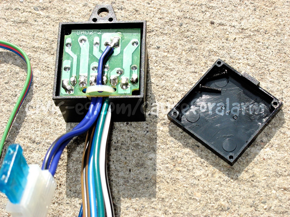
Car Alarm Bench Preparation

One Girls Ocean Challenge » Blog Archive » Race Day LO600
Keyless Entry Help? - Page 2 - iRV2 Forums

2005 f150 door lock wiring

Wiring How To on DEI Viper 451m Type Internal Door Lock Relay ...
Keyless Starter / Power Locks Help - Pennock's Fiero Forum
DEI546 554 IVU User Manual N554V 11-02.qxd DEI Headquarters, .
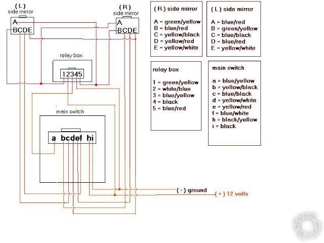
power folding mirrors - Page 2

DIY Aurduino LED Game : 8 Steps - Instructables

DEI 451m wiring? - Page 2

DEI 451m wiring?
5 wire relay/door lock + alarm | TCCoA Forums
Installed Power Door Locks to my JL Sport | Jeep Wrangler ...
Car Alarm Bench Preparation
Directed Electronics 451M Door Lock Relay Assembly Users ...

Dei 451M Door Lock Module Relay Pack Car Remote Start Alarm ...

I have a 2001 Chevy silverado pickup 1/2 4x4. Viper system ...
Central Door Lock Switch to 451M Relay
0 Response to "44 dei 451m wiring diagram"
Post a Comment