43 septic pump float switch wiring diagram
Detailed step by step video of how to wire a septic pump and alarm. Includes control panel with audible alarm, silence switch and red flashing lights; a pump float and an alarm float. 2m x 50m Drain Matting Roll; 2m x 50m Drain Matting Roll; 2m x 200m Drain Matting Roll; 1. Panel AC ammeter wiring diagram with current transformer. Register your CV. Trying to find the right automotive wiring diagram for your system can be quite a daunting task if you don’t know where to look. Luckily, there are some places that may have just what you need. Here’s where to start. Before you search for a...
Pump Float Switch Wiring Diagram With Schematic On Level B2networkco For Dual Septic Tank 6 9 Well Pump Pressure Switch Submersible Pump Well Pump . Collection of float level switch wiring diagram. 3 wire float switch wiring diagram. Jan 24 18 02 09 pm. Let s start with the most basic float switch.

Septic pump float switch wiring diagram
17. jul. 2017 ... Septic system alarms alert the homeowner when an imminent sewage back-up is likely. Inside the septic tank, a float switch tethered to a ... Wiring Diagram For Float Switch - 2012 Ford F350 Fuse Panel Diagram - foreman. Use wiring diagram provided for each version of the Clearstream Control Panel Model series. HOA switch offers either hand, off or automatic operations. HTML PDF: 296-46B-358: Wiring methods and materials—Electrical metallic tubing. Sep 07, 2019 · septic pump float switch wiring diagram – What is a Wiring Diagram? A wiring diagram is an easy visual representation of the physical connections and physical layout associated with an electrical system or circuit.
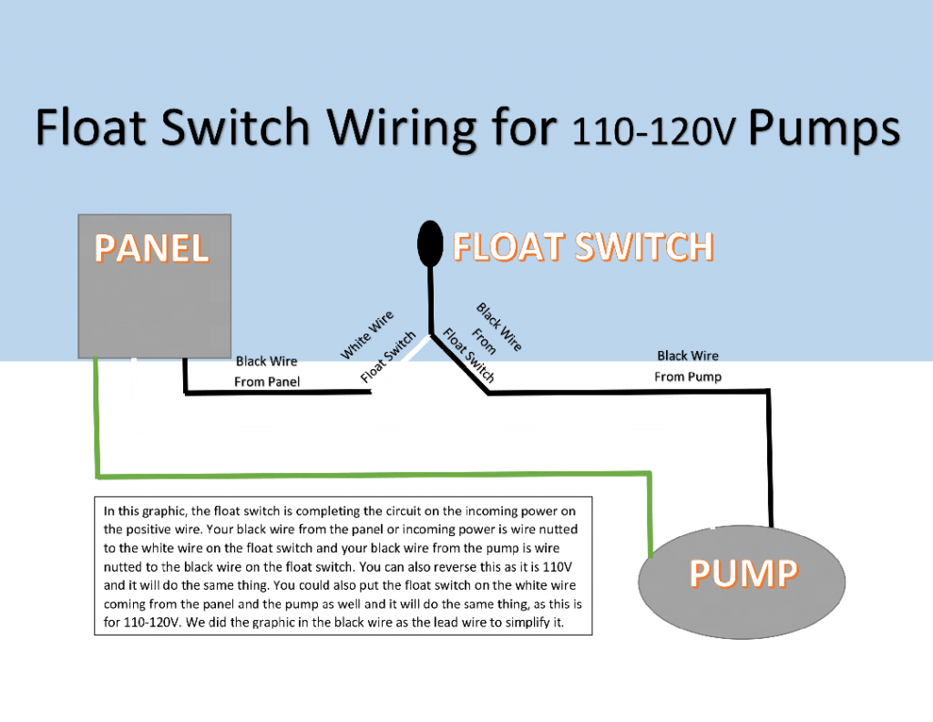
Septic pump float switch wiring diagram. Jan 14, 2019 · The float switch moves with the water level in the tank and this determines when the pump turns on Please note: The information below refers to V pumps and wiring. Below is a diagram of what is described in the paragraph above.Septic Solutions® carries a large selection of septic tank alarms, control panels, and float switches. The septic tank is a very important part of the drainage system in a home. It offers a very safe way of disposing of household wastewater from kitchen, bathroom and toilets. The composition of materials in the septic tank are scum layer, ef... I'm using a contactor because the well installers said that is the way it should be done. They explained that the float switch wiring was too small to run the pump's current through that wire. It's a 3/4 HP submersible pump that they have wired using 10 gauge wire. The float switch model is linked to above. If your septic system uses a pump to remove wastewater from the tank to a drain field, your system will include a septic tank alarm and float switch. When the float rises to an unacceptable level, it sets off an alarm to warn you that your tank may be about to overflow. At times the float switch will malfunction and sound the alarm when the ...
Submersible pumps use float switches to perform automatic operation. The float switch moves with the water level in the tank and this determines when the pump turns on and shuts off. In this article we will discuss the correct way to hard wire a float switch to a submersible pump in order to achieve automatic operation. 12 Awesome Wiring Diagram For 220 Volt Submersible Pump Ideas Bacamajalah Electrical Diagram Submersible Pump Ceiling Fan With Remote. Septic Pump Float Switch Wiring Diagram Tank Fresh Amazing Gallery The Best Electrical Circuit Electrical Circuit Diagram Electrical Wiring Diagram Boat Wiring. Septic Alarm Wiring Diagram. Pump alarm septic tank alarms contractor talk aerobic system faqs q a on tran t2 control panel duplex sewage pumps panels 220 wiring float switch setup for controlonitor systems installation spi bio b double light single phase simplex grinder. Brandywine Septic Services Inc Pump Alarm 610 869 0443. How Single Point & Multi Point Switches Work. In a single point float switch, a low alarm sensor will trigger an LED light on your control board. In a multi point float switch, a low alarm could trigger the LED light to turn on and send a signal to turn on an automatic water pump to refill the water back to the preprogrammed water level. Also, in a multi-point float switch, the process could ...
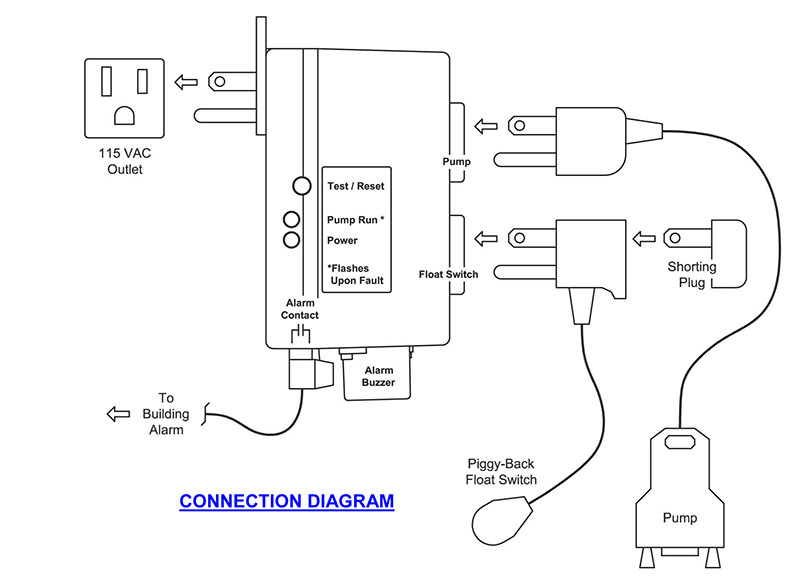
Let's start with the most basic float switch: a two-wire, single-pole, single-throw float switch.The rising action of the float can either close (i.e., turn on) a "Normally Open" circuit, or it can open (turn off) a "Normally Closed" circuit.Installation scenarios might include a Normally Open float switch turning on a pump to empty a tank (Control Schematic 2), or a Normally Closed ... WIRING DIAGRAM Included along with the schematic diagram is a wiring diagram and panel internal layout. Support/bracket design shall provide for no deflection. Step 15: Perform an operational test of the AX-RT float switches and pump(s). Service offered: Control Panel Wiring. STAR-DELTA Starter Without Timer for 3 Phase induction motor. float switches for pumps and control panels Septic Solutions® carries a float switch for every application. Step 14: Install and test the control panel and wiring for the AX-RT unit. The EZ Series® Plugger control panel features a built-in high water alarm and receptacle to accept a 120V or 230V pump and a piggy-back pump switch. Jul 30, 2021 · Septic tank float switch wiring diagram shahsramblings septic tank float switch wiring diagram the diagram provides visual representation of a electric structure. Float switch wiring diagram . Older float switches work by opening and closing circuits dry contacts as water levels rise and fall.
Float switch - Wikipedia
A home or vehicle is a maze of wiring and connections, making repairs and improvements a complex endeavor for some. Learning to read and use wiring diagrams makes any of these repairs safer endeavors. These simple visual representations all...

The Original" Sump Alarm High Water Alarm
pump(s) used. Consult the appropriate float arrangement diagram for the control panel and float arrangement being used. Wire should be sized at 14 AWG for the floats. Refer to the figure below to determine the proper size for the pump wires. When calculating wire size, the length and size of your branch circuit wires

Why does my septic system has separate ON and OFF float ...
Chris shows you how to correctly wire the Double Float pump switches made by SJE Rhombus.The Double Float® pump switch consists of two floats and a splice tu...

Sewage pump float switch explained | Tameson.com
Septic Pump Float Switch Wiring Diagram. Assortment of septic pump float switch wiring diagram. A wiring diagram is a streamlined conventional photographic depiction of an electrical circuit. It shows the parts of the circuit as simplified forms, and also the power and also signal links between the devices. A wiring diagram typically offers info concerning the…

Sump Pump High Water Alarms, Float Switch, Septic Tank ...
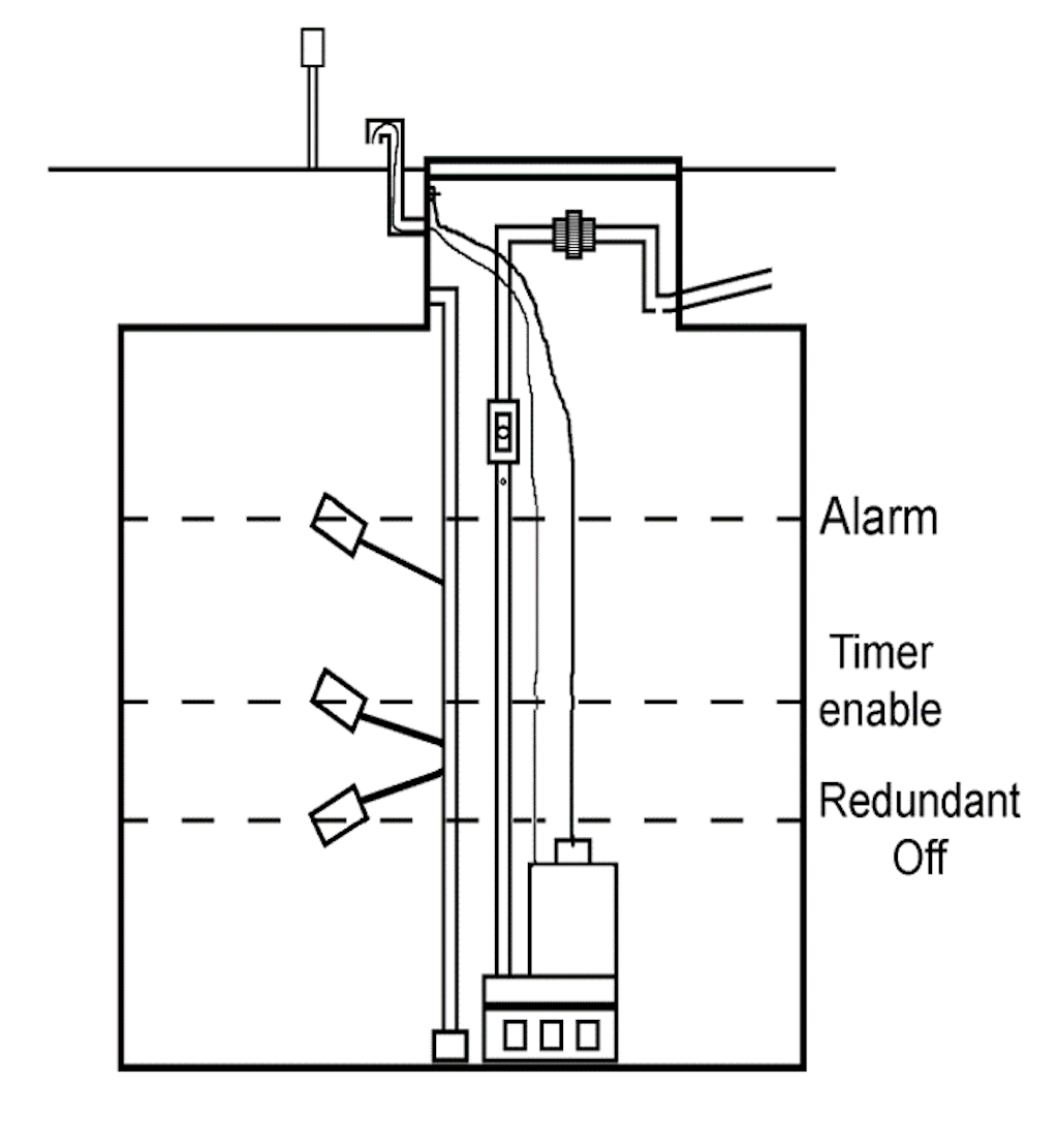
Single-pump (simplex) float switch settings. Top of tank ... Check the assembly against the system's wiring diagram (located in the control panel).

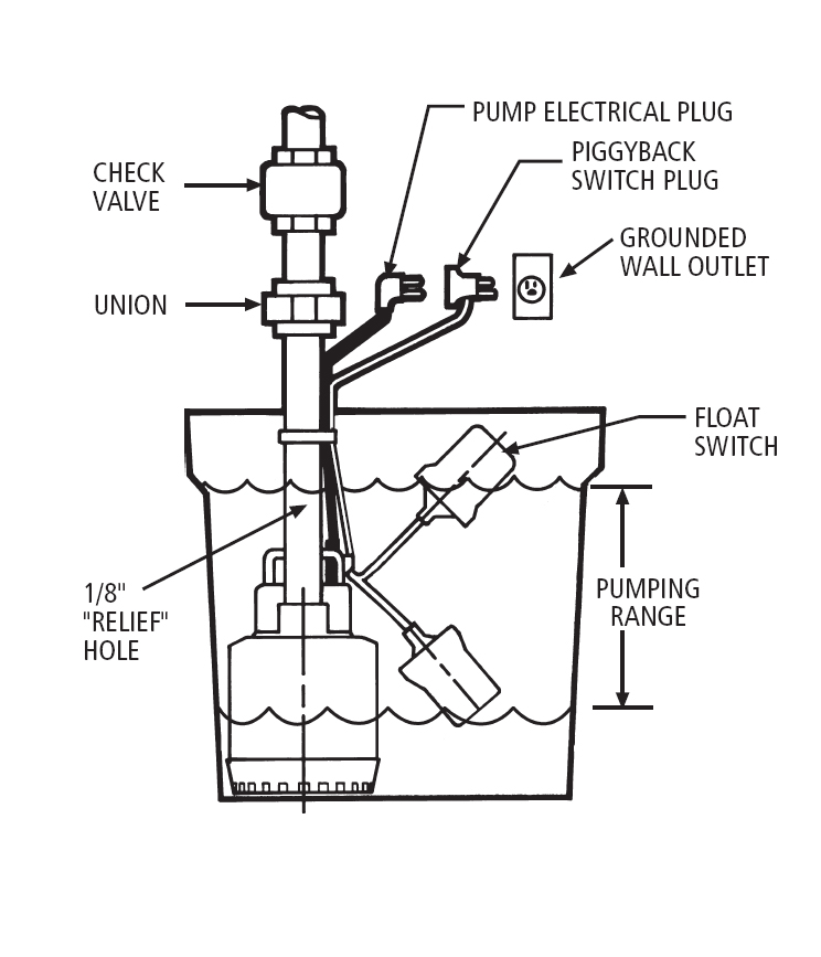
Little Giant 15DFMMD2WOP Double-Float Piggyback Mechanical Float Switch
Dec 11, 2021 · Septic Tank Float Switch Wiring Diagram Fresh Champion Pump Wiring – Septic Tank Float Switch Wiring Diagram. Wiring Diagram arrives with several easy to stick to Wiring Diagram Guidelines. It really is supposed to aid each of the typical person in developing a proper system. These instructions will probably be easy to comprehend and use.

SJE Rhombus Double Float Pump Switch
Water Pump 3 Wire Cable High Temperature Float Switch 3m 5m 10m For Level Manufacturer From China 108407795. 10 Ft Piggyback Float Switch Cable Septic System Sump Pump Water Tank 5 Year Warranty Mercury Free Visible In Sa 3100 3 The. Float switch installation wiring how to wire a submersible pump diagram skyhooks and terry love duplex septic ...
Miami University Department of Engineering Technology ENT 498 ...
About Septic Wiring Control Panel . uk, the world's largest job site. Common applications include sump basins, effluent or sewage pump chambers and lift stations. SUMMARY Wiring of control panels according to engineered wiring diagrams. 4) The grinder pump station is provided with a cable for connection between the station and the.

SJE-Rhombus Model 111 Simplex Single Phase Motor Contactor or Pump Switch Control 120/208/240VAC
June 14th, 2018 - Bilge pump wiring diagram installing float switch to page iboats boating new rule johnson automatic attwood auto 500 JennyLares' 'Wiring Diagram For Bilge Pump Float Switch Wiring Wiring June 22nd, 2018 - Wiring diagram for bilge pump float switch also piggyback float switch wiring diagram furthermore water tank float

Goulds Pump Dealer in Statesville, Mooresville, Huntersville ...
127 Posts. #17 · Jan 27, 2012. If it has two floats, it has a relay in it. white is neutral black is hot and red is switch wire. when the tank fills with water both floats tip up, the short float switches the power to the red wire which starts the pump. when the water level drops the pump turns off when the the long float tips down.
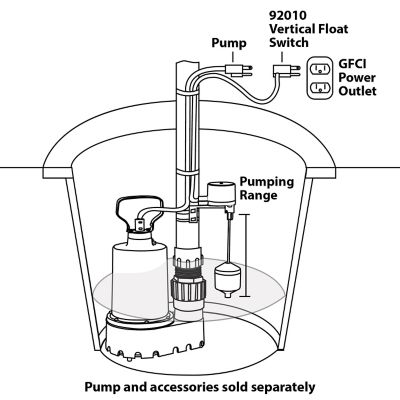
Superior Pump Vertical Float Switch, 92010
How to wire a septic pump.

Correct wiring of float switch into two pole contactor for ...
Enclosure Box I Used: https://amzn.to/2PNw21mAudible Alarm with Float: https://amzn.to/2PKmnslSewage Septic Pump: https://amzn.to/2wlEuNeAlarm with Light and...

Septic Tank Alarm, Float Switch, High Water Alarm, Septic ...
Electrical Layout, Electrical Wiring Diagram, Well Pump Pressure Switch, Submersible Well Pump,. H. John Houston. 209 followers.
Tank Types Express Septic Service
Inputs are typically provided by a single float switch. Industrial control panels come in many sizes and shapes. Model Name/Number: Customer Specified. All Florida Septic is an HCP pump distributor. Installation and Programming Manual. Control Panel Assemblies. Red light and alarm aerobic septic system is going off. lượt xem 33 N2033 năm ...
Installation Manual XLSG200 & XLSGX200 Series 2 HP Grinder ...
Aerobic Septic System Wiring Diagram - This is a image galleries about Septic Tank Float Switch Wiring schematron.org can also find other images like wiring diagram, parts diagram, replacement parts, electrical diagram, repair manuals, engine diagram, engine scheme, wiring harness, fuse box, vacuum diagram, timing belt, timing chain, brakes.
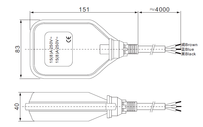
Water Pump 3 Wire Cable Float Level Switch , High Temperature ...
Id 164 Steps In Constructing A Pressure Distribution Septic System. Pump alarm duplex septic sewage pumps aerobic system faqs q a on spex 1 sump and exerciser float switch installation wiring tank alarms contractor talk control panels aquaworx box manual ppt single phase simplex grinder camden supply company inc 220 setup for submersible diagram tran t2 panel high water level with ...

Sump Pump Float Switch Wiring Diagram Gallery | LaptrinhX / News
In this video how to use float switch wiring single phase on off motor using float switch diagram installation for water tank.Hello friendsIn this video, I w...

How to wire a float switch | Tameson.com
Jan 15, 2022 · According to earlier, the traces in a Septic Tank Float Switch Wiring Diagram signifies wires. At times, the cables will cross. But, it doesn’t imply link between the wires. Injunction of 2 wires is usually indicated by black dot to the junction of two lines. There’ll be principal lines that are represented by L1, L2, L3, and so on.

How To Adjust Pressure Switch On Well Pump - unugtp
About Wiring Panel Septic Control . PLC Connection Guide. Modular Patch Panels. Fire control panels. Types of Motor Control Schematics Info Mechanics PICS. The Power Box is a float switch operated control panel. This control panel is designed for use on aerobic treatment systems.

Unique Schematic Symbol Switch #diagram #wiringdiagram ...
12. aug. 2013 ... Mine has a single float that well, floats:laugh: But its small tank/tub for one full basement bath. Line Diagram Parallel. Kenny Bolt on Grab ...
Sump and Sewage Pump Float Settings
Wiring a float switch for 220 septic pump. Bookmark this question. Show activity on this post. I am replacing a 120 volt septic pump with a 240 volt pump controlled by a float switch. How does the float get wired in to shut both legs of the 240 off when the pump is not running? I will be direct wiring it. Pump comes with float already.

Zoeller Pump Company | Qwik-Box Control and Alarm
The float switches for sump and sewage pumps are known to fail, sometimes all too frequently. The creator of this video believes the failures are due to the...
New help using 2 floats switches on Feed water tank ...
Step 2: Mount The Float Switch. Float switch installation requires you to mount the device with some way of fixing the cable above the tank or well. There is a mounting bracket available for the Kari Float Switch that uses a snug wedge to fix the cable into place. This bracket can be attached to a wall or a rail using a simple bolt or screw.
Item # SPEx-1, Sump and Sewage Pump Exerciser® Controllers ...
See the Electrical Wiring Video #2 Below: Septic System Lift Pump and the Float Switch. [ad#block] Electrical Question: I recently re-wired a receptacle for the lift pump for my septic system. The previous home owner had buried the cable under ground and the over the years the cable deteriorated and corroded and eventually shorted out.

Improve pump float switch reliability with a relay or contactor
Septic Tank Alarm Wiring Diagram. Pump alarm aerobic septic system faqs q a on duplex sewage pumps control panels tran t2 panel alarms controlonitor systems tank contractor talk sump high water float aquaworx box installation manual spi bio b double light. Brandywine Septic Services Inc Pump Alarm 610 869 0443.

How do I wire a 110 float switch to a 220 pump? Its a 220 v 1 ...
Sep 07, 2019 · septic pump float switch wiring diagram – What is a Wiring Diagram? A wiring diagram is an easy visual representation of the physical connections and physical layout associated with an electrical system or circuit.
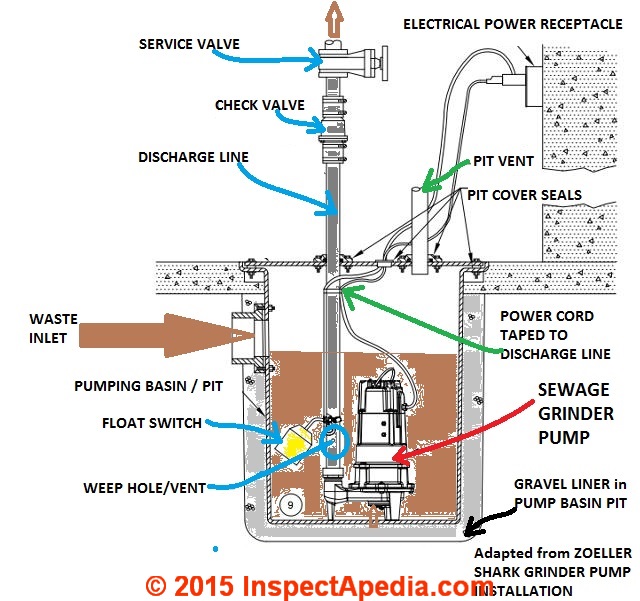
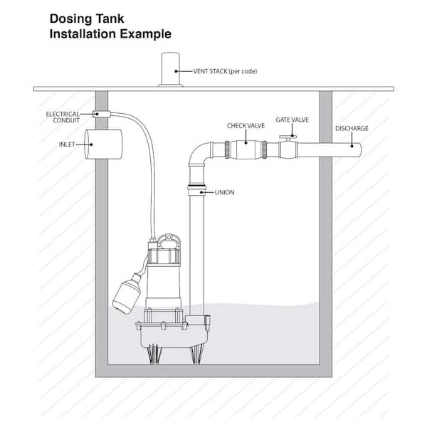
Septic pump installation guide
Wiring Diagram For Float Switch - 2012 Ford F350 Fuse Panel Diagram - foreman. Use wiring diagram provided for each version of the Clearstream Control Panel Model series. HOA switch offers either hand, off or automatic operations. HTML PDF: 296-46B-358: Wiring methods and materials—Electrical metallic tubing.
Piggyback required? Can I direct wire? - RIDGID Forum ...
17. jul. 2017 ... Septic system alarms alert the homeowner when an imminent sewage back-up is likely. Inside the septic tank, a float switch tethered to a ...
PUMP STATION START-UP and TROUBLESHOOTING MANUAL
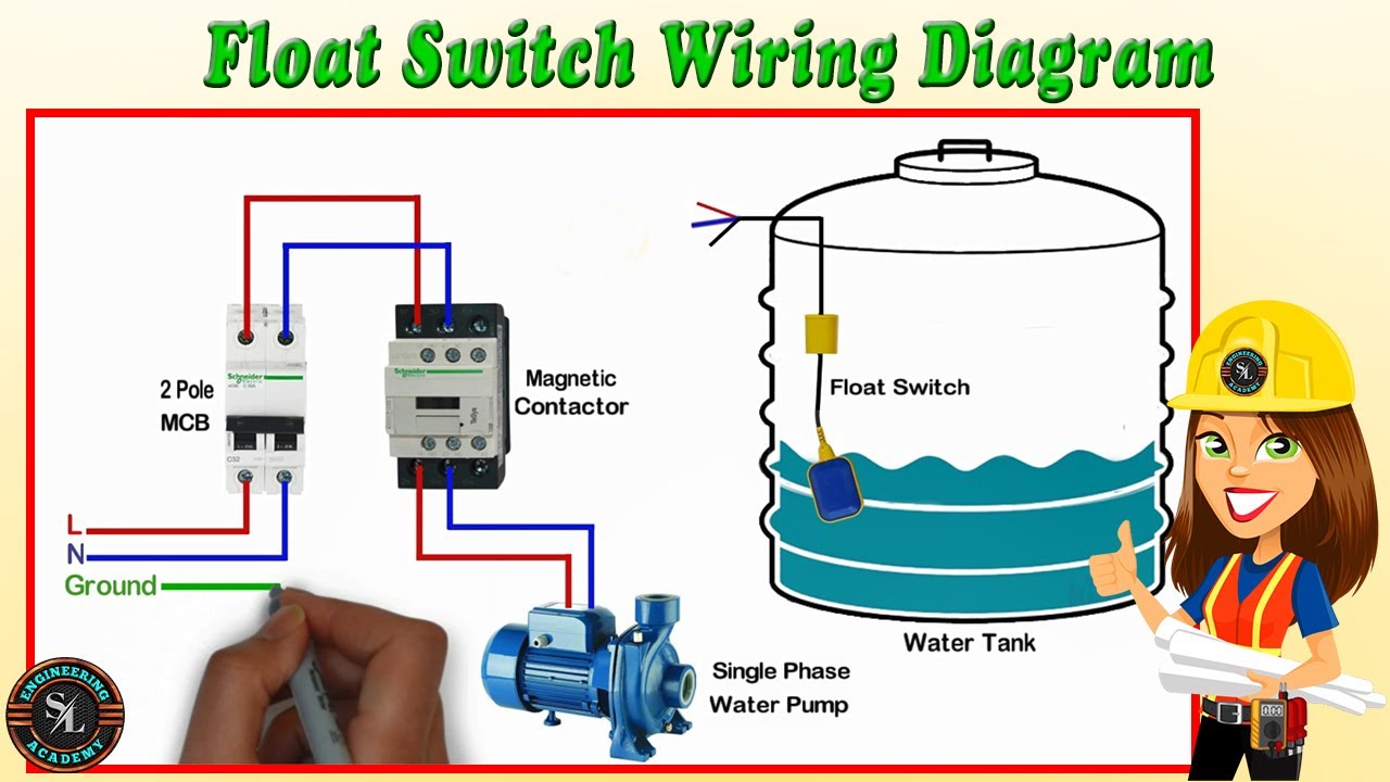
Float Switch Wiring Diagram for Water Pump/ How to Make Automatic On-Off Switch for Water Pump

Float Switch - How They Work | Tameson.com

Septic Control Panels - Wholesale Septic Supply | Wholesale ...
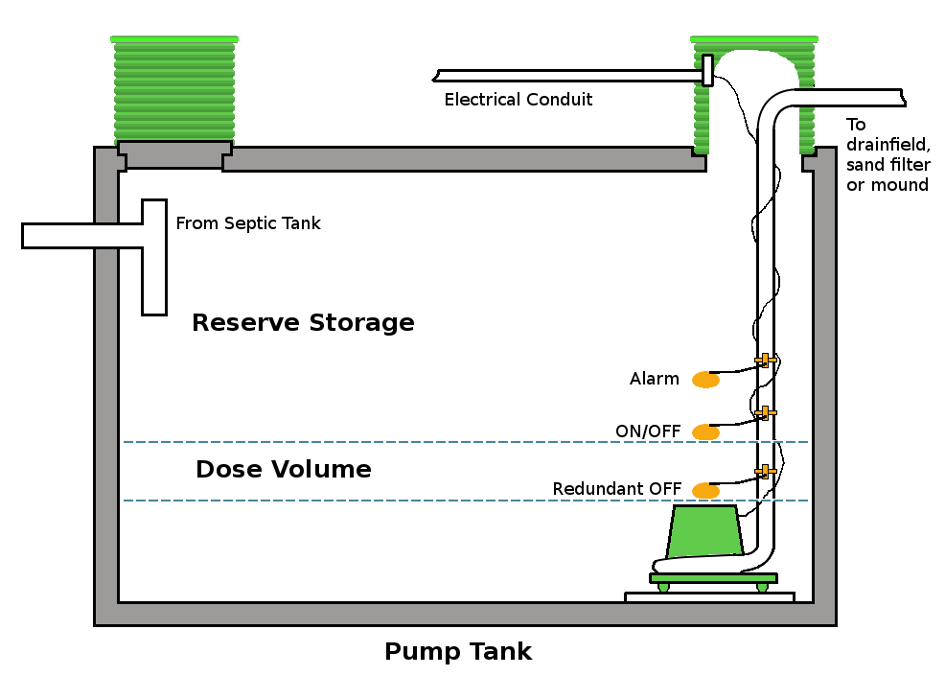
Benefits of Time Dosing and Flow Equalization | Onsite Installer

Duplex Septic & sewage pumps: buy & installation guide to ...

I have a septic lift pump that has two floats. The pump was ...
Piggyback required? Can I direct wire? - RIDGID Forum ...
Everbilt 1/2 HP Effluent Pump with Tethered Switch HDEFR50W ...

Float Switches and Mounting Brackets | Zoeller Engineered ...

Install a Septic System Tank Solution
How To Wire A Submersible Pump - Aerobic Septic System

Float Switches and Mounting Brackets | Zoeller Engineered ...

Rotjoart (akanorotimi) - Profile | Pinterest
220 wiring/ float switch setup for septic effluent pump ...
0 Response to "43 septic pump float switch wiring diagram"
Post a Comment