43 marine voltmeter wiring diagram
How to Install a Voltmeter on Your Boat - LiveAbout Here's a very simple do-it-yourself project with useful benefits such as detecting or preventing a power problem on your boat. Most boats have 12-volt electrical systems powered by one or more batteries that are recharged by the engine's alternator or other electrical sources such as solar panels or a wind generator. If you don't already have a voltmeter wired into your system to keep you ... Digital Ampere and Voltmeter Wiring Diagram - YouTube Digital Ampere and Voltmeter Wiring DiagramYou can Buy that DC Digital Ampere and Voltmeterhttps://amzn.to/31McekJDigital Voltmeter Ammeter Wiring DiagramDC ...
AC And DC Voltmeter Wiring Diagram Voltmeter wiring diagram and volt meter instillation for (AC) alternating and (DC) direct current with Urdu / Hindi video tutorial.
Marine voltmeter wiring diagram
Voltmeter Wiring Diagram - uniport.edu.ng October 6, 2021 - The official website of the University of Port Harcourt PDF Voltmeter — Instructions VOLTMETER — INSTRUCTIONS WIRE NUT FLAT WASHER NUT WASHER VOLTMETER GROMMET U-BRACKET DO NOT LEAVE ANY HARDWARE OUT OF THESE CONNECTIONS Diagram 1 ground source (Step 2) should be connected as shown in Diagram 1, to the voltmeter's connection post marked "-". 5. The wire from the fuse box (Step 3) should Voltmeter wiring diagram | Sailboat Owners Forums 6 Mar 2001 — Hi Folks: I am replacing my ammeter with a voltmeter on my Atomic 4. The wiring harness I saw on a previous answer only works for the diesel ...
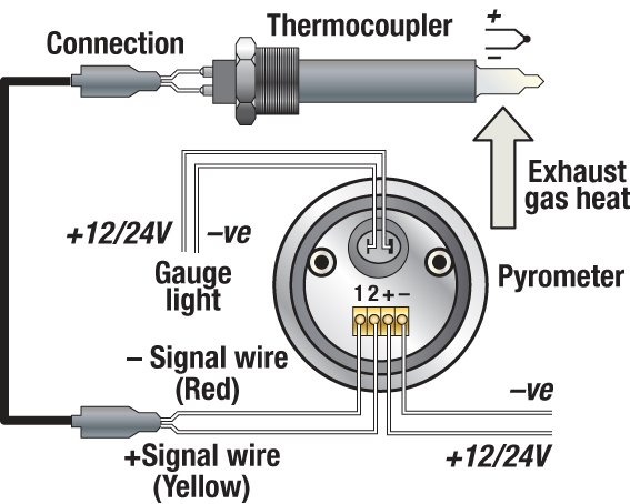
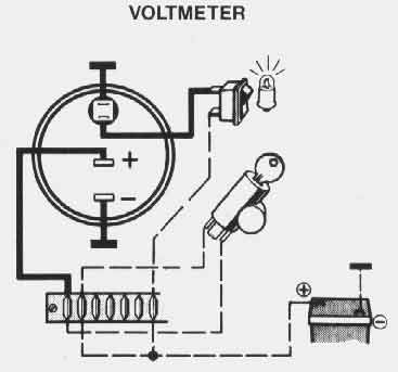
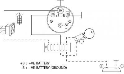
Marine voltmeter wiring diagram. How to Hook Up a Marine Voltmeter - Gone Outdoors A voltmeter allows you to keep track of the amount of electricity flowing through your boat's electrical system. If your boat's entire DC electrical system operates at the same voltage, whether it is 12VDC, 24VDC or 48VDC, you can install the voltmeter anywhere in the boat's electrical system. 0 515 012 068 -- Voltmeter.p65 - VDO Instruments JavaScript seems to be disabled in your browser. You must have JavaScript enabled in your browser to utilize the functionality of this website · Since 1920, we’ve been focused on providing our customers with the best possible instrumentation. We continue to work to deliver the functionality, ... Voltmeter 12/24 Illustration A - VDO Gauges JavaScript seems to be disabled in your browser. You must have JavaScript enabled in your browser to utilize the functionality of this website · Welcome Gauge Enthusiast PDF Marine Electrical Installation Marine Electrical Analog DC ... ampere fuse in the positive lead near the source. Do not connect the voltmeter in a series (in-line) configuration. Series Installation 4. Installation of Backlight • Connect the yellow negative wire to a DC ground. • Connect the red positive wire to any 12V DC positive supply, or connect the orange positive wire to any 24V DC positive supply.
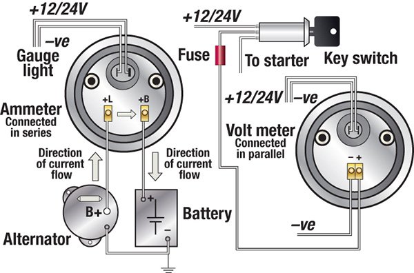
Ammeter wiring | Boat Design Net It doesn't need to be as heavy as the starter wire because it will never carry more than 40 Amps. In new installations nobody uses Ammeters anymore because of the heavy wiring and/or losses. A voltmeter showing the range of 10-15V is much easier to implement. Vdo Volt Gauge Wiring Diagram - easywiring Thesamba com gallery vdo volt gauge wiring diagrams performance instruments diagram boat tuli anb3 vmbso de voltmeter png 1200x1200px me 0386 auto by type displays and cers so 4984 marine hour meter trim 22 joke alexandra brueckner vision black series library. Lamp socket 1 3. Vdo gauge installation and troubleshooting guides. Fusion-Link Wireless Remote App | Fusion Entertainment A ... May 28, 2019 · A Fusion remote control network powered from the stereo - this is enabled from the settings menu on compatible Fusion stereos. The required wiring is supplied with the remote. A Fusion remote control network powered from a 12V supply - this requires a NMEA power cable (Fusion PN: CAB-000541) to build a network (see diagram below) SUPER EASY Boat Wiring and Electrical Diagrams - YouTube **Full Parts List Below:***Amazon Electric Section: ***Switch Panels, A...
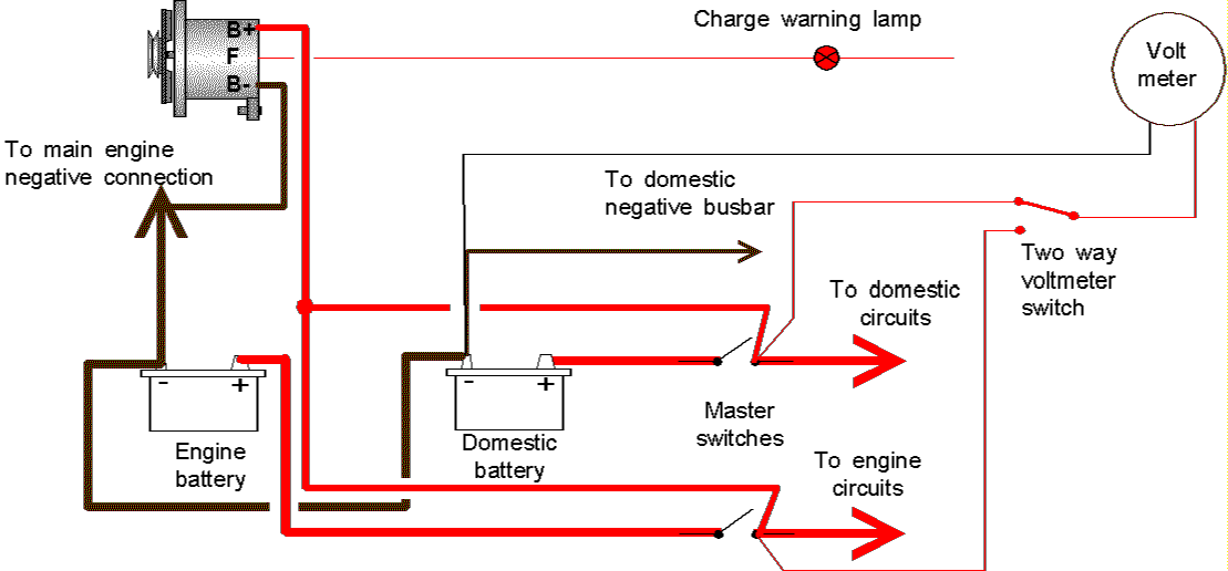
Installing Digital Volt Meters (DVM) on Your Boat - Seaboard ... September 20, 2019 - Battery terminal voltage by means of a digital voltmeter wired direct to the battery allows you to always “see” what is happening throughout your charging and discharging periods. Only then can you fully understand what is happening where it matters most, at the battery itself. Engine Instrument Wiring Made Easy - Boats.com Engine Instrument Wiring Made Easy. Engine instrument gauges fall into three categories, and there are differences in the terminals and wiring. By Ed Sherman. June 6, 2014. The vast majority of recreational boats in service today are still using analogue instrumentation systems. More modern digital, NMEA-networked, and multifunction gauges may ... Vdo Gauges Wiring Diagrams - schematron.org Wiring diagrams. 2 - 9.Vdo ammeter wiring diagrams moreover wiring diagram for gauge along with marine voltmeter wiring diagram in addition fuel gauge wiring diagram boat further marine gauges wiring diagram in addition album page furthermore wisconsin wiring diagram ammeter along with auto gauge tach wiring diagram furthermore faria fuel gauge ... How to Install an Auto Meter Pro-Comp Ultra-Lite Voltmeter Gauge ... Auto Meter Pro-Comp Ultra-Lite Voltmeter Gauge; Electrical (Universal; Some Adaptation May Be Required) ... As a safety precaution, the 12V wire attached to the positive I ( ) terminal of the gauge should be fused before connecting to the positive ( ) output side of the ignition switch.
INSTALLATION INSTRUCTIONS: Viewline 52 mm
Boat Voltmeter Wiring Guide: Hook Up Voltimetear Easy And ... January 6, 2022 - If you are a boat owner, a voltmeter is one of the accessories you want to be installed in your vessel. Not only will it allow you to track the amount of electric power running through the boat’s electrical system but also helps you determine whether the battery is working properly.

Buy JULAU Quick Charge USB Car Charger 3.0 Dual with ...
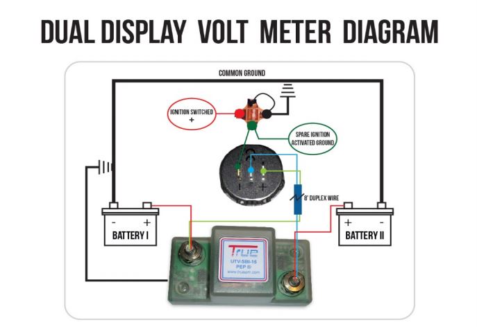
Meters - Gauges - Monitors - New Wire Marine Voltage and Current Monitoring Meters. There are two primary bits of information that indicate the status and rate of change of your electrical system, which is displayed on: Voltmeters display of course voltage. In this application, the voltage is useful because it shows the level of charge of your battery. A 12V (nominal) battery will top off ...
Battery Watering Systems, Marine Dock Products, Solar Dock ...
Volt meter wiring? | Boating Forum - iboats Boating Forums Hello forum, I have a 1986 125hp Force that I am going through the dash wiring on. I got the overheat alarm working and am now having trouble with the volt meter. Mine has a ground post, a "P" post (positive 12V I assume) and a "S" post (I assume send or signal?) Post "P" I am hooking up to a...

Volt meter and Amp meter - ROUND
Smiths Voltmeter Wiring Diagram - U Wiring 16 Awesome Wiring Diagram Simple For You Trailer Wiring Diagram. Wiring instructions for 60 0 ammeter boat design net 60a electric e 12v digital voltmeter led amp meter 2in1 dc 100v catalog to the power supply 1929 a 6v diagram help 10a blue red. Motley Mods Box Mod Wiring Diagrams Led Button Switch Parallel. Smiths Gauges On New.

Installing two voltmeters | Sailboat Owners Forums
3 Battery Boat Wiring Diagram - Pinterest Boat Audio Wiring Diagram Fresh Marine Dual Battery Wiring. Boat Audio Wiring Diagram ... Wiring Diagram Electric Oil Pressure Gauge New Equus Voltmeter.
/GettyImages-185079661-59146e603df78c9283b46618.jpg)
How to Install a Voltmeter on Your Boat
How To Wire A Boat | Beginners Guide With Diagrams | New ... Even a small boat (3-5 loads) we'd recommend at least 12AWG wire for this. 10AWG for larger boats (5-10 loads) is normal. 8AWG is getting toward over-kill in most cases for boats under 30ft. Remember these are all generalities, there are many valid reasons to make exceptions.
Troubleshooting Boat Gauges, Instruments and Meters | BoatUS
Voltmeter Diagram Wiring - U Wiring Voltmeter Diagram Wiring. Amarante Pruvost. November 6, 2021. I did not touch the existing amp meter wiring. Connect the red lead of your voltmeter to each B battery voltage supply coming into the RCM module connector and the black lead of your voltmeter to a good. Pin On For Inpiration.
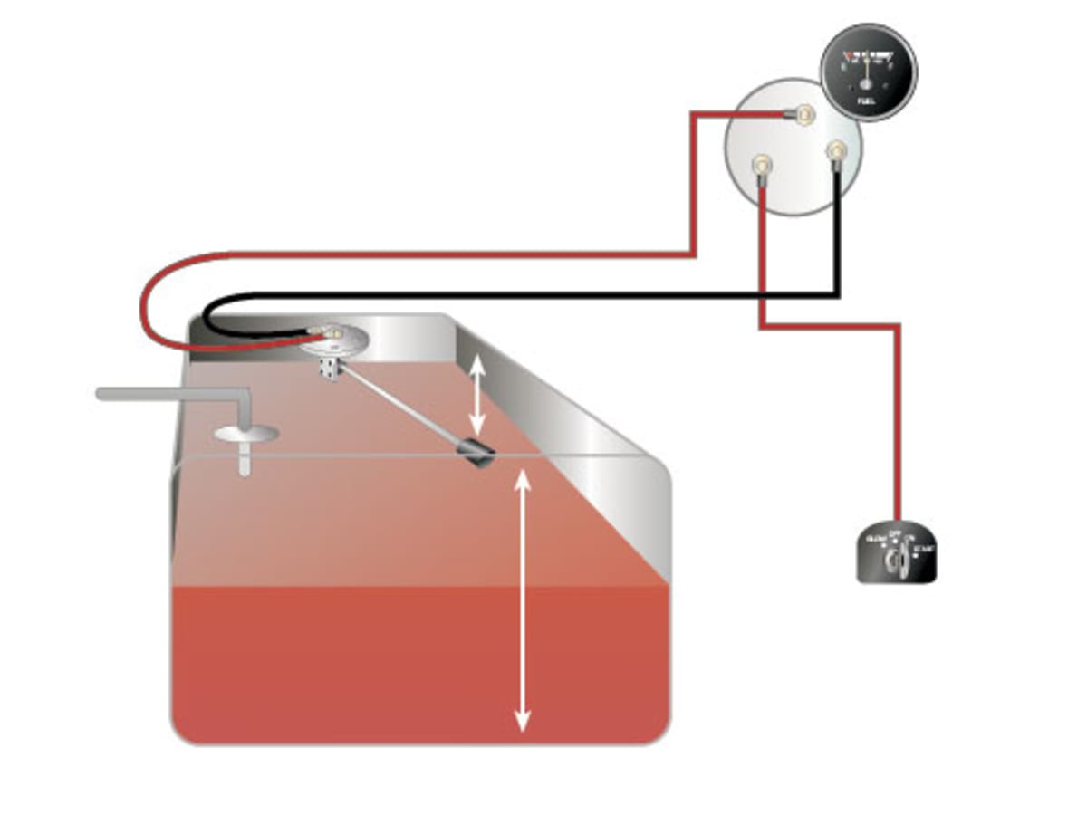
How to Test and Replace your Fuel Gauge and Sending Unit ...
Voltmeter Ammeter Wiring Diagram | Volt ampere, Function generator, ... Jul 5, 2018 - This Pin was discovered by Jim Neufeld. Discover (and save!) your own Pins on Pinterest
Results page 521, about 'short circuit detector'. Searching ...
PDF Caution - Faria Beede 2" Voltmeter 12 & 24 VDC systems IS0004 Rev. F ecn 6933 07/2007 Caution Installation 4. Connect a wire to the gauge stud marked "+" (positive) and secure with a nut and lock washer. Connect the opposite end to a circuit that is activated by the ignition switch. It is recommended that insulated wire terminals, preferably ring type, be

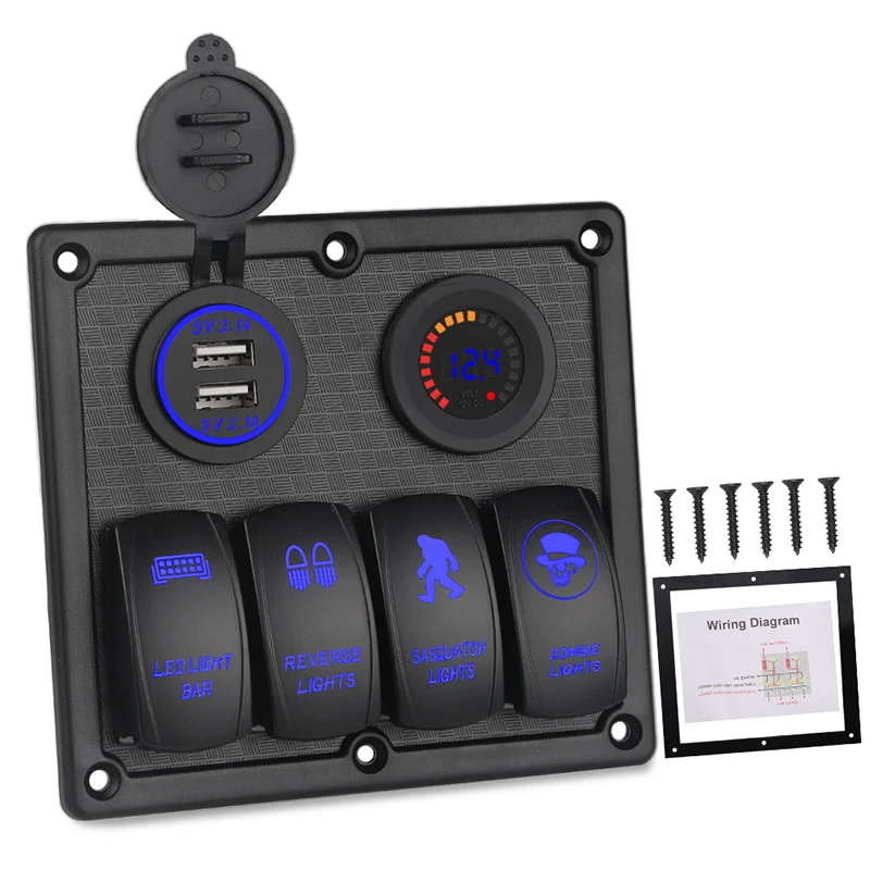
Switch Panel with Volt Meter, Dual USB Socket Charger 12V 4.2A&LED Voltmeter&Cigarette Lighter Socket&ON/Off Rocker Switch 4 in 1 Panel for Boat ...
How to Wire a Voltmeter - DoItYourself.com Step 6 - Connect Positive Wire. Use one of the wires that you found in the wiring harness and cut it between the steering column and connector in the dash. Connect the end coming from the steering column to the voltmeter. Take the piece of 16 gauge wire and complete the circuit by connecting it to the connector wire.
Installation Instructions
Voltmeter Wiring Diagram - TR4/4A Forum - TR Register Forum August 22, 2010 - Would anyone advise as to the correct wiring for a voltmeter on a TR4a please, or a wiring diagram would be great. Best regards Lee
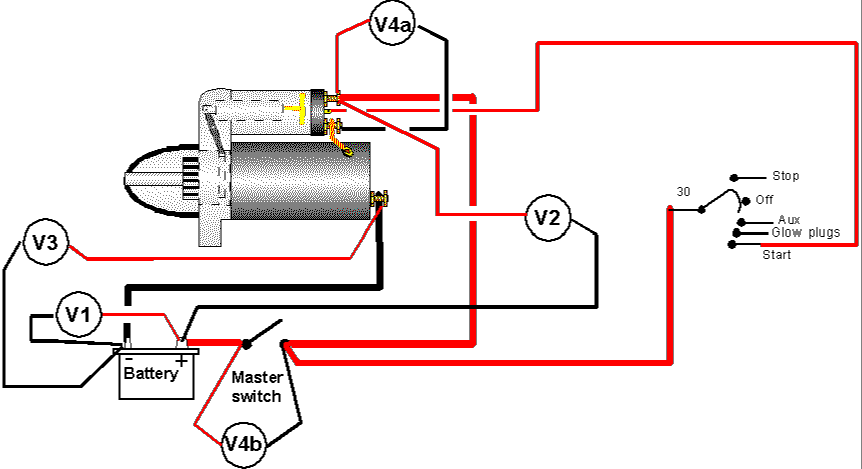
DC Wiring Diagram - Moyer Marine Atomic 4 Community - Home of ...
Installation Instructions - Ammeter - Faria Beede Manufacturer of dash instruments and advanced telematics reporting devices.
Troubleshooting Boat Gauges, Instruments and Meters | BoatUS
Best place to connect volt meter? - The Hull Truth - Boating and ... May 30, 2013 - Marine Electronics Forum - Best place to connect volt meter? - I am installing a volt meter on my boat as it makes me nervous not to keep tabs on the

VOLTMETER INSTALL (aftermarket)
PDF Installation Analog AC Voltmeter - Blue Sea the source. Do not connect the voltmeter in a serial (in-line) confi guration. Wiring Diagram for AC Voltmeters (Installation (continued) 4. Calibration The voltmeter is calibrated at the factory and recalibration should never be necessary. However, if adjustment does become necessary the needle may be reset to the zero mark.
VDO Performance Instruments
How to Wire Voltmeter Gauges on a Car | It Still Runs Electricity is a valubale commodity, especially in modern automobiles. There was a time when all an electrical system really had to do was run an ignition system, headlights, tail lights, and maybe a radio or AC blower. Now, drivetrains are shot through with electron-driven devices; fuel pumps, ...

LED Digital Multimeter Voltmeter Ammeter for Car Boat Marine ...
Automotive Voltmeter Wiring Diagram June 21, 2019 - These free automotive wiring diagrams tips are actually your short cuts to electrical troubleshootingonce you understood how to use it you ...

Quick Charge 3.0 Car Charger, Waterproof 12V/24V Aluminum Dual QC3.0 USB Fast Charger Socket Power Outlet with LED Digital Voltmeter & Wire Fuse DIY ...
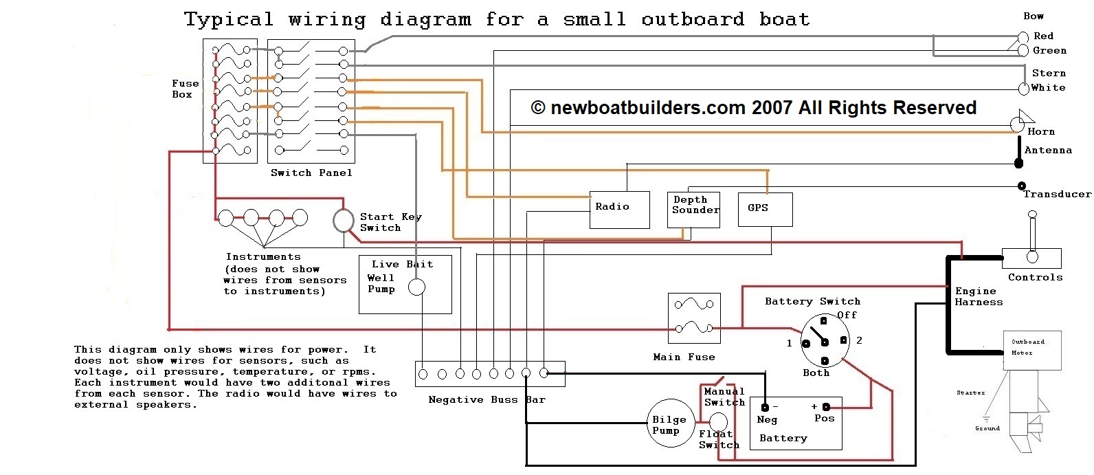
Basic 12 Volt Boat Wiring Diagram - Wirings Diagram As stated previous, the lines in a Basic 12 Volt Boat Wiring Diagram represents wires. Sometimes, the cables will cross. However, it does not imply link between the wires. Injunction of 2 wires is usually indicated by black dot at the intersection of 2 lines. There will be main lines that are represented by L1, L2, L3, and so on.
ME10
Voltmeter Selector Switch Connection Diagram November 22, 2020 - A guide about voltmeter selector switch connection diagram for 3 phase system and 3 phase 4 wire system, or how to wire use voltmeter selector switch.
Installing An LED Voltmeter In Your Boat - Battery Level Check
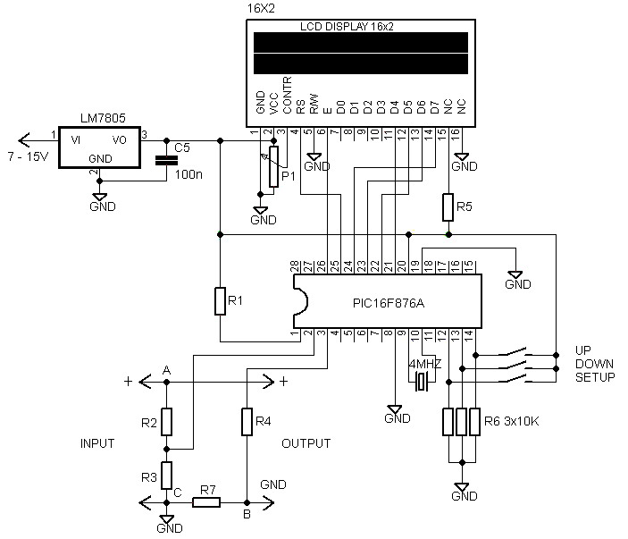
How to wire digital dual display volt- and ammeter - DIY Projects October 23, 2019 - How to wire "Chinese" 10A/100V volt- and ammeter gauges which have shunt built-in? There is many of them with different colored wires. Here I share wiring for most common ones with plain simple schemas.
3 4 6 8 Gang Boot Usb Autolader Voltmeter Rocker Panel Switch ...
(PDF) Basic Electrical Installation Work, Fourth Edition ... Academia.edu is a platform for academics to share research papers.
Installation Instructions
VDO Documentation - VDO Marine Gauges VDO Cylinder Head Temperature Gauge Handlebar/Fairing Mount - 2009. VDO Resitive Gauge wiring Instructions - 2009. Veratron Flex Gauge 52mm NMEA2000 12/24v. ViewLine 52mm Wiring Diagram (2014) ViewLine Standard Resistive Gauges 52mm Installation Sheet (2014) Viewline Temperature Gauges 12/24 Volt (2011) Viewline Temperature Gauges 52mm (2008)

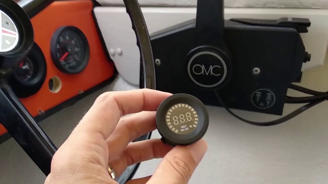
Where To Hook Tach To On Ignition Key Switch On An Omc ...
Voltmeter Connection Diagram For AC/DC February 5, 2021 - In this post, I write about voltmeter wiring for the AC single-phase and DC with a simple voltmeter connection diagram.
Voltmeter 12 volt inbouwmeter
Ammeter Circuit Diagram - U Wiring Ammeter Wiring Diagram wiring diagram is a simplified good enough pictorial representation of an electrical circuit. The completed wiring of the voltmeter ammeter with the power supply. Amp Gauge Wiring 1 Always disconnect the ground lead from the vehicle battery before wiring any gauge. The circuit diagram of multi range DC ammeter is shown in ...

Buy Switch Panel, FABOOD 3 Gang Waterproof Rocker Switches ...
Voltmeter wiring diagram | Sailboat Owners Forums 6 Mar 2001 — Hi Folks: I am replacing my ammeter with a voltmeter on my Atomic 4. The wiring harness I saw on a previous answer only works for the diesel ...
Boat Building Standards | Basic Electricity | Wiring Your ...
PDF Voltmeter — Instructions VOLTMETER — INSTRUCTIONS WIRE NUT FLAT WASHER NUT WASHER VOLTMETER GROMMET U-BRACKET DO NOT LEAVE ANY HARDWARE OUT OF THESE CONNECTIONS Diagram 1 ground source (Step 2) should be connected as shown in Diagram 1, to the voltmeter's connection post marked "-". 5. The wire from the fuse box (Step 3) should

2-1/16
Voltmeter Wiring Diagram - uniport.edu.ng October 6, 2021 - The official website of the University of Port Harcourt
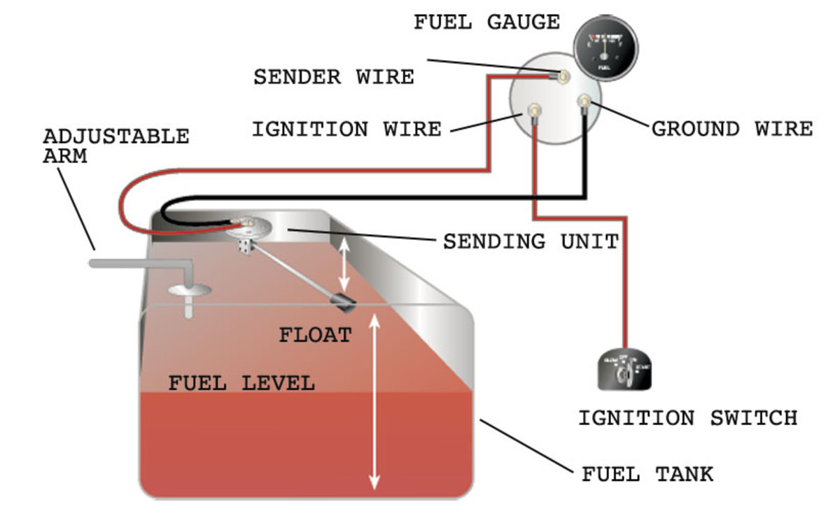
How to Test and Replace your Fuel Gauge and Sending Unit ...

2-5/8
ME06

Mini OLED Boat Voltmeter | Panel Mount | Blue Sea 1733 | New ...
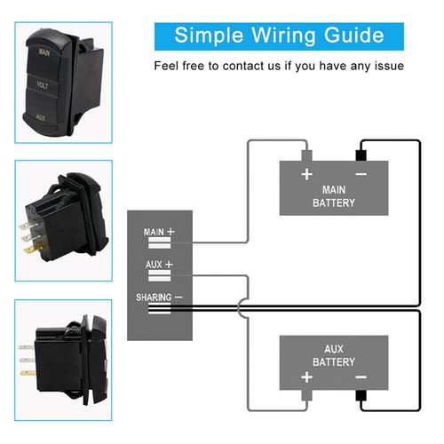
12v dual battery isolator wiring diagram car boat marine
Engine Instrument Wiring Made Easy - boats.com
Voltmeter under Repository-circuits -24870- : Next.gr

Troubleshooting Boat Gauges, Instruments and Meters | BoatUS

6 Gang Auto Toggle Rocker Switch Panel Met Zekering Overbelasting Bescherming 12V Sigarettenaansteker Voltmeter 5 V 3.1a Usb power Charger
Installation Instructions
Dual Batterij Systeem Monitor Voltmeter Inbouw Boot Marine ...
10-60V Dual Voltmeter Gauge LED Digital Panel Volt Battery ...

High Quality 4 Gang 12V Blue LED Voltmeter on/off 4.2A Dual ...

Install Guides - Solid Kit

Building a basic volt meter -Freetronics Forum
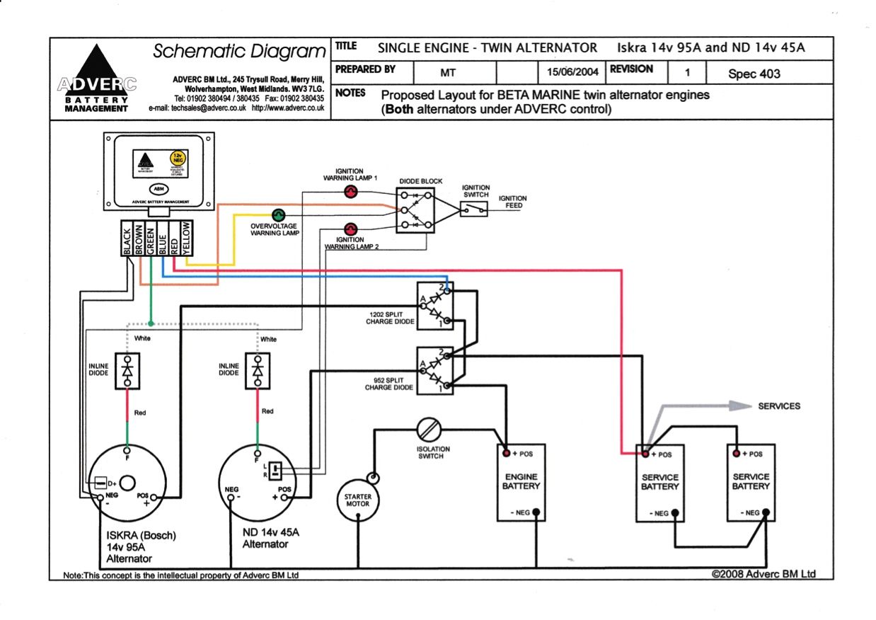
Wiring diagram for Beta 38 with C-type control panel - Boat ...

Quick Charge 3.0 USB Charger Socket Dual USB Car Power Outlet ...
0 Response to "43 marine voltmeter wiring diagram"
Post a Comment