42 ray diagram for converging lens
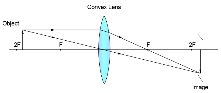
Jul 09, 2018 · Convex lens can converge the parallel rays to a point (focal point) since it is known as converging. Ray Diagrams for Lenses. The image formed by a single lens can be located and sized with three principal rays. Examples are given for converging and diverging lenses and for the cases where the object is inside and outside the principal focal length. Ray tracing diagram for a converging lens, with the object beyond twice the focal length. (yes, the light actually bends at both surfaces, not the middle of ...
Student understanding of the real images produced by converging lenses and concave mirrors was investigated both before and after instruction in geometrical optics. The primary data were gathered t...

Ray diagram for converging lens
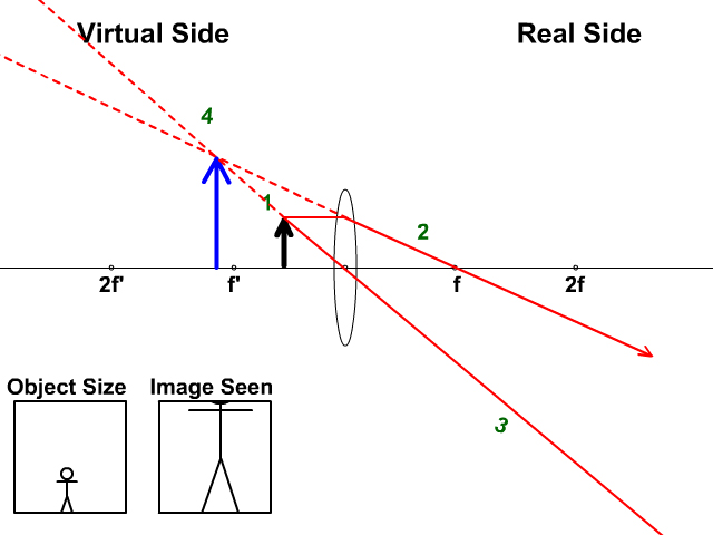
The Physics Classroom » Curriculum Corner » Refraction and Lenses » Ray Diagrams for Converging Lenses. The document shown below can be downloaded and printed. Teachers are granted permission to use them freely with their students and to use it as part of their curriculum. Visit the Usage Policy page for additional information. Ray diagram for converging lens. Ray 1 is parallel to the axis and refracts as if from F. Ray 2 heads towards F’ before refracting parallel to the axis. Ray 3 passes straight through the center of the lens. image is always virtual, upright and reduced O F I F’ Ray diagram for diverging lens It can be derived from a geometric analysis of ray tracing for thin lenses and is given by. The magnification of an image is the ratio between the image and object... Recall the five basic rules of ray tracing: A ray entering a converging lens parallel to its axis passes through the focal point F of the lens on the other side....
Ray diagram for converging lens. Ray Diagrams For Diverging Lenses. The top diagram shows the formation of the virtual object where converging rays are prevented from meeting by the diverging lens. enter image. In this lab, you will construct the TWO ray diagrams for diverging lenses. In each diagram, use an arrow, cm tall, pointing upwards as the object. Patents Contact lens for the display of information such as text, graphics, or pictures Abstract The Contact Display is a system that allows the wearer to... 1 is a diagram depicting a contact lens 100 incorporating a diffractor. The optical axis 101 of the contact lens 100 defines the central axis of sight 102. In this way... In this section of Lesson 5, we will investigate the method for drawing ray diagrams for objects placed at various locations in front of a . To draw these ray diagrams, we will have to recall thefor a double convex lens: Any incident ray traveling parallel to the principal axis of a converging lens will refract through the lens... Diverging Lenses As such, the rules for how light behaves when going through a diverging lens is a little bit different. You will be expected to be able to draw a Ray Diagram of a converging and diverging lens on our upcoming test without the rules.
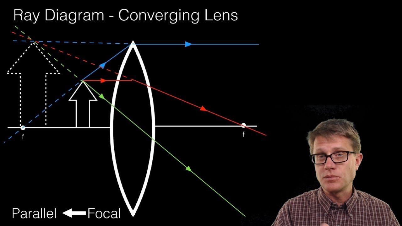
The ray diagram constructed earlier for a diverging lens revealed that the image of the object was virtual, upright, reduced in size and located on the same side... the lens reduced in size (i.e., smaller than the object) Unlike converging lenses, diverging lenses always produce images that share these characteristics. The... (10) Draw a ray diagram for a 3.0-cm tall object placed 10.0 cm from a converging lens having a focal length of 15.0 cm. (11) Draw a ray diagram for a diverging lens that has a focal length of -10.8 cm when an object is placed 32.4 cm from the lens's surface. (12) Draw a ray diagram for an object placed 6.0 cm from the surface of a converging lens with a focal length Convex Lens Ray Diagrams For lenses, the following three rays are typically used in ray diagrams. Keep in mind that an inflnite number of rays actually form the image. Ray # 1 For a lens, the flrst ray starts from the top of the object and extends parallel to the optical axis to the center of the lens. This ray, for a converging (convex) lens, Oct 30, 2014 · Trick to drawing ray diagrams for converging lens: There is one ray of light passing through the center of the lens. Always. 2 rays are enough to determine the position of image/object. The other ray of light ALWAYS passes through the focal point of the lens. Either the first focal point of the second focal point.
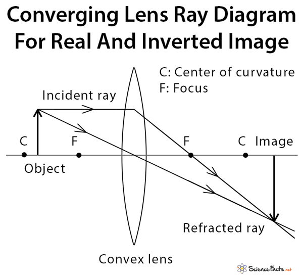
A converging lens produces a focused real image 2.1 cm from the lens of an object that is 6.8 cm from the lens. a. Draw a ray diagram for this configuration. b. Find the focal length of the lens. c. Step-by-Step Method for Drawing Ray Diagrams. The method of drawing ray diagrams for double convex lens is described below. The description is applied to the task of drawing a ray diagram for an object located beyond the 2F point of a double convex lens. 1. Pick a point on the top of the object and draw three incident rays traveling towards the ... Ray Diagrams for Lenses. Three principal rays can be used to locate and size the image formed by a single lens, with examples for converging and diverging lenses. The three principal rays are:. A ray from the top of the object proceeding parallel to the centerline perpendicular to the lens, passing through the principal focal point beyond the lens. According to an interview with Insider, Andreas Schwieger of Leitz Photographica Auction believes the lens for sale is one of the half-dozen lenses that were supplied to NASA. It's a fascinating lens. Of the four copies that weren't sent to NASA for use in space, three were sent to filmmaker Stanley Kubrick for the film 'Barry...
For converging lens, draw a ray diagram for an obj that's ...
The picture shows rays from a distant object reaching a converging lens with a focal length of 5 cm. Complete the ray diagram to show how the converging lens forms an image.
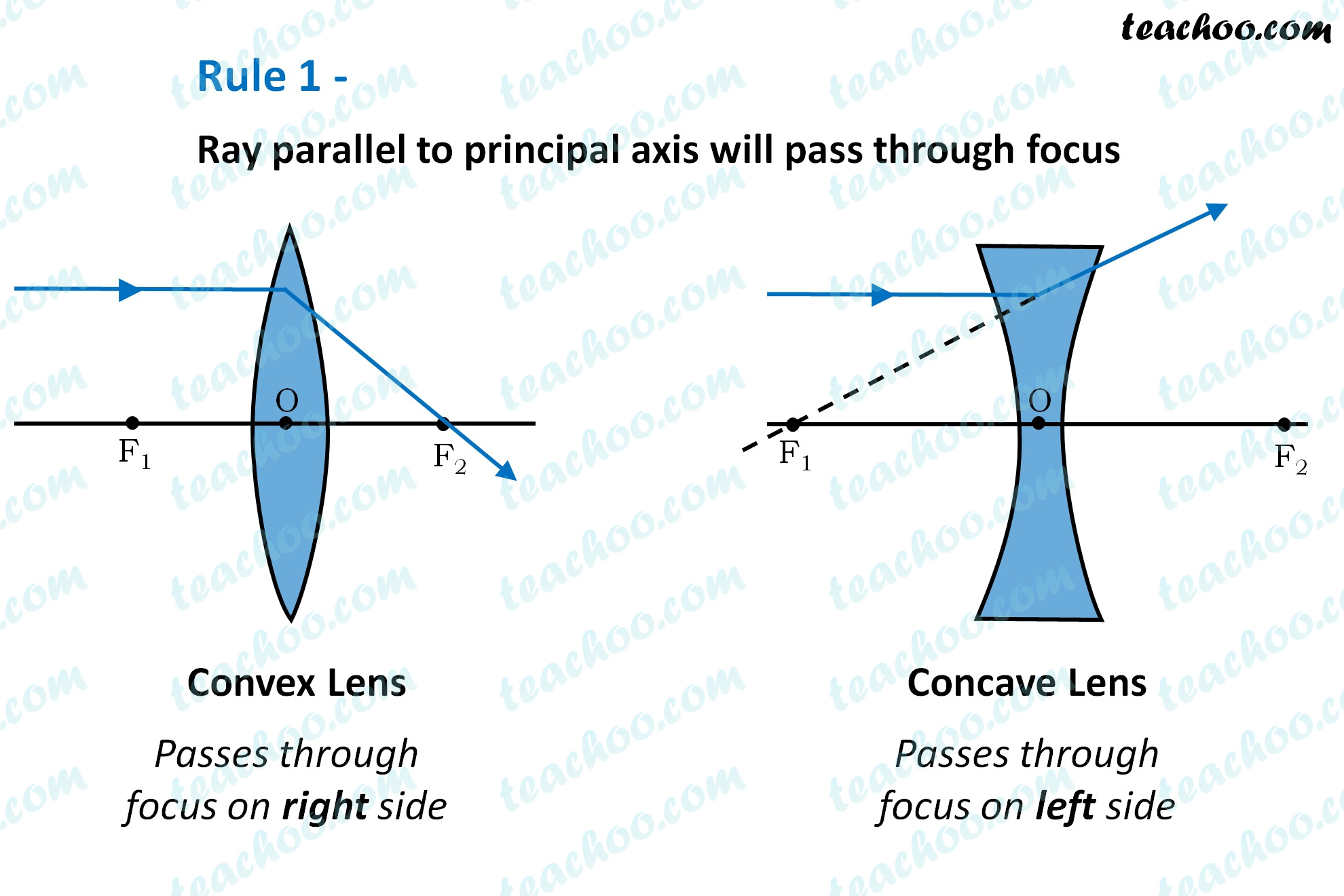
Rules for drawing Ray Diagram in Convex and Concave Lens ...
Description of how to draw ray diagrams for converging lenses for grade 10 science.

Lenses- Convex lens- Ray Diagrams
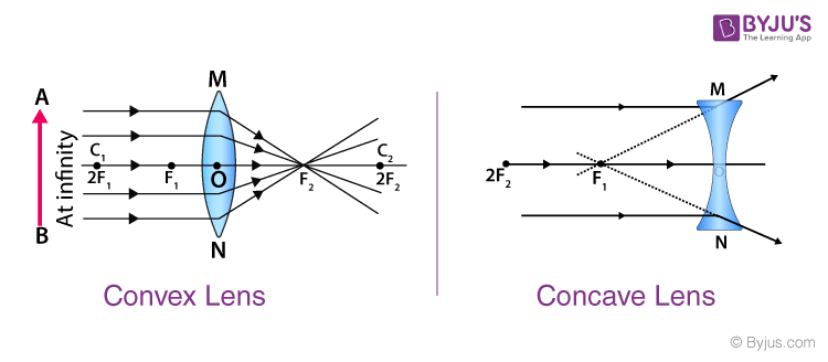
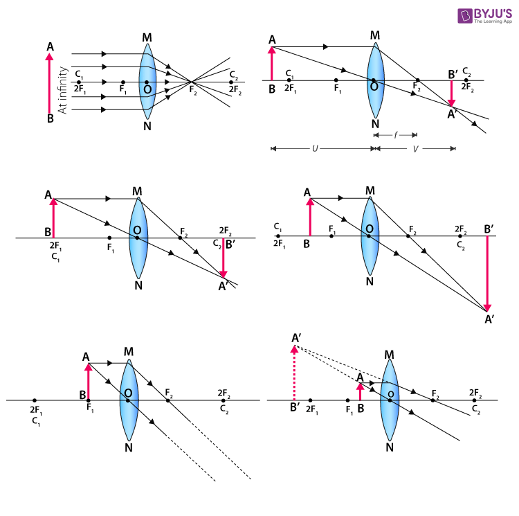
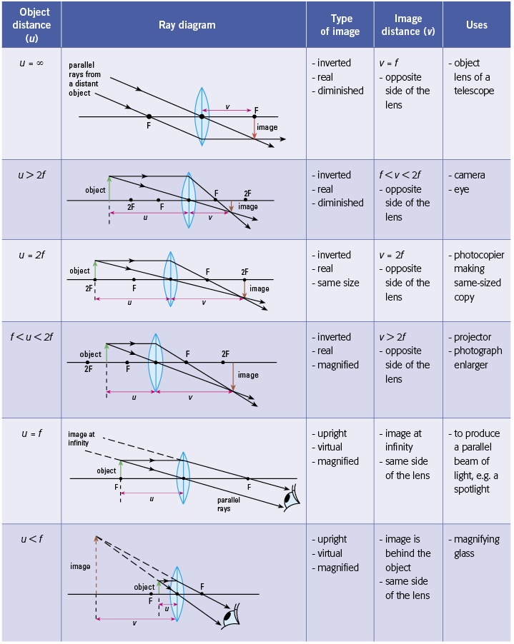
Convex Lens - Ray diagram. Last updated at Nov. 18, 2021 by . For a Convex Lens, object can be kept at different positions Hence, we take different cases Case 1 - Object is Placed at infinity In this Case, Object is kept far away from lens (almost at infinite distance)

Converging lens ray diagram - Lens D
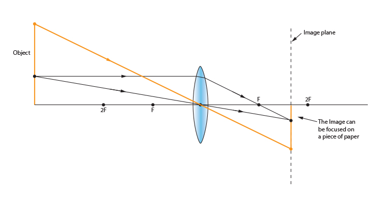
Real images occur when objects are placed outside the focal length of a converging lens (s>f). If the lens is converging but the distance from the object to the lens is smaller than the focal length, the image will be virtual. Diverging lenses always produce virtual images. This calculator shows a ray diagram when the image is real. Magnification

Ray diagrams for image formation of (a) converging (bi-convex ...
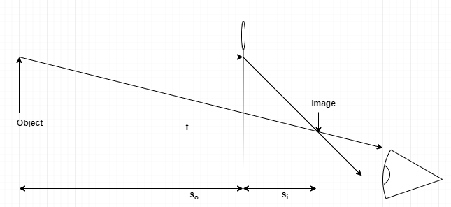
Here you have the ray diagrams used to find the image position for a converging lens. You can also illustrate the magnification of a lens and the difference between real and virtual images. Ray diagrams are constructed by taking the path of two distinct rays from a single point on the object. A light ray that enters the lens is an incident ray.

Converging+and+Diverging+Lenses.pdf - Converging Diverging ...
Waves 저자:Martti Sloan Ray diagram for converging lens Lens Pair 다음 Ray diagram for converging lens 새 자료 Open Middle: Distance, Midpoint, Slope (3) Open Middle: Creating Trig EQ's Exercise Set Chebyshev Polynomial of the First Kind Spelling Wordle Open Middle: Distance, Midpoint, Slope (1) 자료 찾기 Moving Tangent Line... Waves Ray diagram for converging lens Lens Pair GeoGebra 정보 파트너십 평가 뉴스 피드 앱 다운로드 앱 계산기...

Simplest Way To Draw Ray Diagrams For Convex Lenses | Grade 10-12
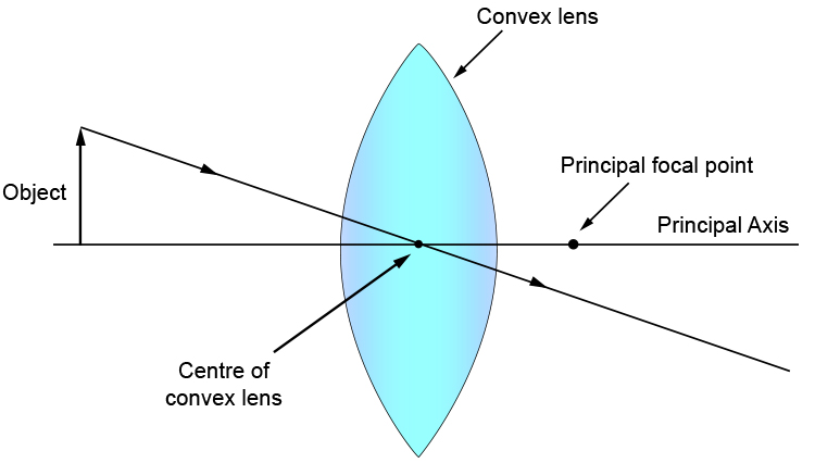
A convex lens is thicker in the middle than it is at the edges. Parallel light rays that enter the lens converge. They come together at a point called the principal focus. In a ray diagram, a ...
Physics Tutorial: Refraction and the Ray Model of Light
Lens, in optics, piece of glass or other transparent substance that is used to form an image of an object by focusing rays of light from the object. A lens is a piece of transparent material, usual...

Converging lens Images, Stock Photos & Vectors | Shutterstock
A converging lens that is curved on both sides (there are two types of converging lens- concave and convex.) A converging lens causes the light rays that are travelling parallel to its principal axis to refract and cross the principal axis at a fixed point called the focal point. (This is explained in more detail below). (A ray diagram is given ...
Physics Tutorial: Refraction and the Ray Model of Light
A ray diagram using this virtual object shows the location of the final image (bottom part of Figure O). Numerically, we can verify the accuracy of the ray diagram with: An arrow is placed 50 cm away from a converging lens (f= 25cm). On the other side of this first lens is a second converging lens (f. Ray Diagrams for Lenses. The image formed ...

Sketch a ray diagram for a spherical convex lens with an ...
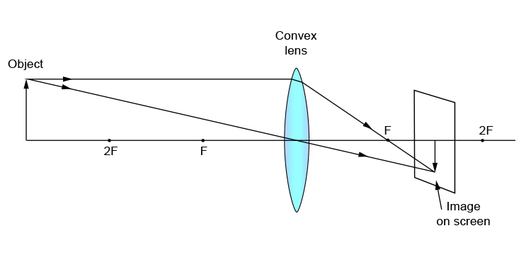
Ray diagram for an object placed between 2F and F from a convex lens In a film or data projector, this image is formed on a screen. Film must be loaded into the projector upside down so the ...
I made this diagram to help clarify ray diagrams and optics ...
A thin converging lens forms an image of an object, as shown in the diagram. 2 Only one ray is shown in the diagram. On the diagram, draw two more rays from point X on the object that can be used to locate point Y on the image. [2] [Total: 2] Which ray diagram shows a converging lens forming a real image of a small object O? 3 O A O B O C O D [1] 2

Draw a ray diagram to show formation of a virtual image of an ...
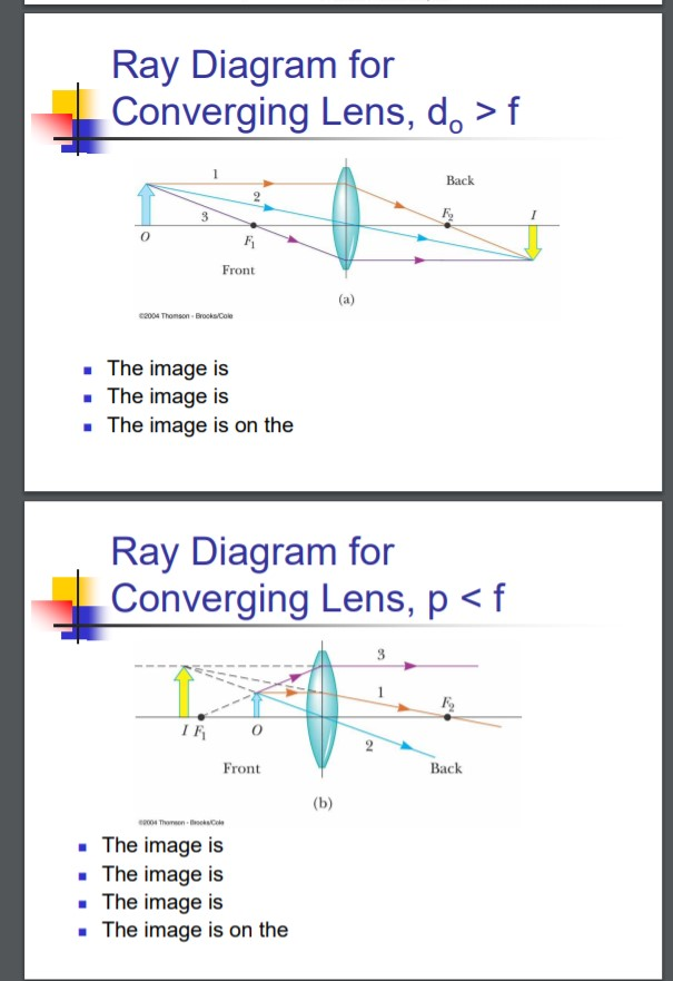
Ray diagram for converging lens Ray 1 is parallel to the axis and refracts through F. Concave Mirror Ray Diagram Concave Mirror Ray Diagram lets us understand that when an object is placed at infinity a real image is formed at the focus. Ray 2 passes through F before refracting parallel to the axis.

The Photons Of Light Then Travels In All Directions - Simple ...
Previous work conducted with converging solid switchable lenses generally comprise a lens-shaped cavity filled with a LC, which experiences a reduction of focal... (a) shows a diagram of the design used for the switchable LC lens. The base curve of the lens is designed to fit on the eye, with a radius of curvature of 7.8 mm...

Which diagram shows rays of light passing through a ...
Most recently, the Synopsys optical engineering team designed the Mastcam-Z zoom lens for the Mars Perseverance rover that landing on Mars in February 2021. The, which functions as the rover’s mast-mounted scientific “eyes.” The “Z” in Mastcam-Z stands for “zoom.” It represents a milestone in the history of space...
Concave and Convex Lenses - Image Formation | Curvature & Focus
Ray Diagrams for Lenses The image formed by a single lens can be located and sized with three principal rays. Examples are given for converging and diverging lenses and for the cases where the object is inside and outside the principal focal length. The "three principal rays" which are used for visualizing the image location and size are:
Ray Diagrams for Lenses
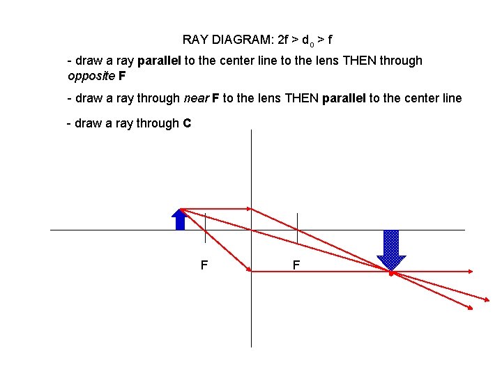
Step-by-Step Method for Drawing Ray Diagrams. The method of drawing ray diagrams for double convex lens is described below. The description is applied to the task of drawing a ray diagram for an object located beyond the 2F point of a double convex lens. 1. Pick a point on the top of the object and draw three incident rays traveling towards the lens.
Lens Ray Diagram Practice
A recently published patent from Canon details a set of optical formulas for what appears to be an RF 90mm F2.8L IS Macro lens. Japanese Patent Application Number 2018-205435, first detailed by Northlight Images , is fairly standard as far as patents go, but there is one interesting element worth noting. The image stabilization...

SOLVED:Part 3: Convex Converging Lenses Usc the light box t0 ...
This Demonstration lets you visualize the ray diagrams for converging and diverging lenses. By manipulating the object and lens locations, you can create real or virtual images. The rays parallel to the principal axis and the ray through the center of the lens are drawn.Locators allow you to drag both the object and the lens. You can change the focal length using a slider.
Draw a ray diagram for a converging lens w... | Clutch Prep
• Light rays bent towards each other… CONVERGING LENS. • The less parallel the two sides, the more the light ray changes direction. • Rays from a single point, converge to a single point on the other side of the lens (and then start diverging again). We build lenses out of glass with non-parallel sides Put film, Retina here!
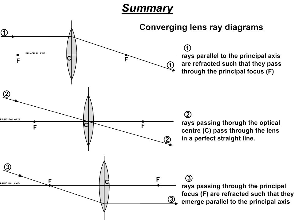
Waves Drawing ray diagrams for converging lenses. - ppt download
Converging and diverging lenses ray diagrams worksheet answers pdf The image formed by a single lens can be located and sized with three principal rays. Examples are given for converging and diverging lenses and for the cases where the object is inside and outside the principal focal length. The "three principal rays" which are used for ...
Convex lens and objects larger than the lens
Thin Lens Equation Converging and Dverging Lens Ray Diagram & Sign Conventions, Physics - Optics: Lenses (1 of 4) Converging Lens, Thin lens equation and problem solving | Geometric optics | Physic...

✓ Solved: The top row of Figure CQ23.3 shows three ray ...
Sub-aperture lens correctors for single-mirror telescopes PAGE HIGHLIGHTS • Meniscus corrector • Jones-Bird • Ross corrector • Wynne corrector • Paracorr... FIGURE 154: LEFT: Ray spot diagram for 200mm f/5.9 system with f/4 spherical primary and Jones-Bird type corrector (Telescope Optics, Rutten/Venrooij), placed in... telescopeѲptics.net ▪ ▪ ▪▪▪▪▪▪▪▪▪ ▪ ▪ ▪ ▪ ▪ ▪ CONTENTS ◄10....
To Find Image Distance For Varying Distance Of A Concave Lens
Interactive demonstration of ray diagrams (converging or diverging lenses and mirrors, prism).Fixed glitch in ray rendering for the converging lens with object distance < F. Thanks for the physics teacher reporting the bug. Prism reshaping rewritten to keep the same light source orientation.
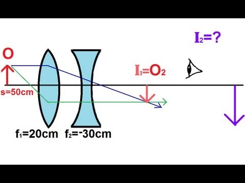
Physics - Optics: Lenses (4 of 5) Lens Combinations - Converging & Diverging Lenses
While a ray diagram may help one determine the approximate location and size of the image, it will not provide numerical information about image distance and image... This falls into the category of for a converging lens. Now lets try a second sample problem: A 4.00-cm tall light bulb is placed a distance of 8.30 cm from a...
Convex lens - object at more than `2F`
It can be derived from a geometric analysis of ray tracing for thin lenses and is given by. The magnification of an image is the ratio between the image and object... Recall the five basic rules of ray tracing: A ray entering a converging lens parallel to its axis passes through the focal point F of the lens on the other side....
SS: Ray Diagrams For Converging Lens - Mini Physics - Learn ...
Ray diagram for converging lens. Ray 1 is parallel to the axis and refracts as if from F. Ray 2 heads towards F’ before refracting parallel to the axis. Ray 3 passes straight through the center of the lens. image is always virtual, upright and reduced O F I F’ Ray diagram for diverging lens
Ray Diagram PRELAB LAB
The Physics Classroom » Curriculum Corner » Refraction and Lenses » Ray Diagrams for Converging Lenses. The document shown below can be downloaded and printed. Teachers are granted permission to use them freely with their students and to use it as part of their curriculum. Visit the Usage Policy page for additional information.

A) Draw a ray diagram for the following si... | Clutch Prep
Converging Lens: Definition, Diagram, Equation & Application
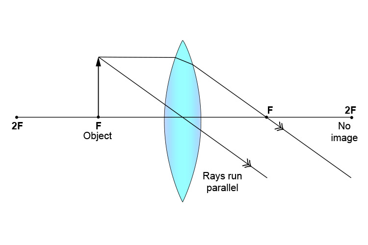
Convex lens - object at `F`
RAY DIAGRAMS FOR LENSES CONVEX CONVERGING LENS All
Convex lens - object between `2F` and `F`
Method for drawing ray diagrams - convex lens
Ray Diagrams - Lenses
Lenses and images: Physclips - Light
Ray Diagrams for Lenses
Physics Tutorial: Refraction and the Ray Model of Light

Draw a ray diagram to show how a converging lens is used as a ...

Drawing ray diagrams for a converging lens - The Fizzics ...

Determining Focal Lengths of Concave and Convex Lenses ...
Solved Ray Diagram for Converging Lens, d. >f Back Front ...
0 Response to "42 ray diagram for converging lens"
Post a Comment