44 3 phase motor wiring diagram pdf
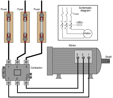
Jan 15, 2022 · The wiring diagram for connecting thee phase motor to the supply along with control wiring is shown in figure below. 3~3~ L1 L2 L3 N Suggested wiring arrangement SELECTOR SWITCH HI SPEED CONTACTOR OVERLOAD OVERLOAD LO SPEED CONTACTOR These diagrams are current at the time of publication, check the wiring diagram supplied with the motor. 3 phase motor starter wiring diagram pdf source. It shows the parts of the circuit as simplified shapes and also the power and also signal links in between the tools. 3 Wire Submersible Well Wiring Diagram Get Free Circuit Diagram Electrical Circuit Diagram Capacitors The first step is to figure out the voltage of your phases.
D. The following are the connection diagrams for STANDARD 3-phase general purpose 9-lead and 12-lead dual voltage motors. For all other connections such as two speed motors, 1-phase motors, alternate starting methods, etc., consult factory. 9 LEADS 12 LEADS Thermal Protection The motor nameplate will indicate whether the motor is thermally ...

3 phase motor wiring diagram pdf
TWO-SPEED MOTORS For all other SINGLE-PHASE wiring diagrams refer to the manufacturers data on the motor. Diagram DD6 Diagram DD8 M 1~ LN E Diagram DD9 M 1~ LN E White Brown Blue L1 L2 N S/C Bridge L1 and L2 if speed controller (S/C) is not required Diagram DD7 LN E L1 L2 N S/C Z2 U2 Z1 U1 Cap. Thermal contacts (TB) white M 1~ Z2 - Yellow (AUX ... TWO-SPEED MOTORS For all other SINGLE-PHASE wiring diagrams refer to the manufacturers data on the motor. Diagram DD6 Diagram DD7 M 1~ LN E Diagram DD8 LN E L1 L2 L3 S/C Z1 U2 Z2 U1 Cap. Thermal contacts (TB) white M 1~ Z2 - Yellow Z1 - Blue U2 - Black U1 - Red Bridge L1 and L2 if speed controller (S/C) is not required M 1~ LN E White Brown ... 3 phase motor starter wiring diagram pdf source. A wiring diagram is a streamlined conventional photographic representation of an electrical circuit. Ac manual starters and manual motor starting switches 12 class 2510 12 class 2511 and 2512 13 2 speed ac manual starters and. Phase 2 l1 l2 l3. They can be used as a guide when wiring the controller.
3 phase motor wiring diagram pdf. Capacitor Motor Single-Phase Wiring Diagrams ALWAYS USE WIRING DIAGRAM SUPPLIED ON MOTOR NAMEPLATE. W2 CJ2 UI VI WI W2 CJ2 UI VI WI A cow VOLTAGE Y HIGH VOLTAGE z T4 Til T12 10 Til T4 T5 ALI L2 T12 TI-BLU T2-WHT T3.ORG T4-YEL T5-BLK T6-GRY T7-PNK T8-RED T9-BRK RED TIO-CURRY TII-GRN T12-VLT z T4 Til T12 Wiring Diagram Book A1 15 B1 B2 16 18 B3 A2 B1 B3 15 Supply voltage 16 18 L M H 2 Levels B2 L1 F U 1 460 V F U 2 ... OVERLOAD RELAYS AC MOTORS DC MOTORS WIRING CAPACITORS RESISTORS SEMICONDUCTORS Table 1 Standard Elementary Diagram Symbols (cont'd) ... 1-Phase 2-Phase, 4-Wire 3-Phase Line Markings L1, L2 L1, L3: Phase 1 L2, L4: Phase 2 L1, L2, L3 3 phase motor starter wiring diagram pdf - You will need a comprehensive, expert, and easy to comprehend Wiring Diagram. With this kind of an illustrative manual, you'll have the ability to troubleshoot, stop, and total your tasks without difficulty. Oct 30, 2021 · Figure 1 is a typical wiring diagram for a three-phase. Electrical panel wiring diagrams. Basic wiring for motor control ac circuits worksheet circuit diagram pdf direct online starter of a three phase how 3 works using plc ladder and reversing troubleshooting on off electric programmable controller single forward reverse motors.
for delta and wye 9-lead motors. In addition, the 12-lead motor requires connecting wire-nut 10, 11, and 12 together. The following diagram illustrates these connections graphically: Wye connected 12-lead wiring diagram Wye connected 12-lead motors differ from 9-lead three-phase dual-voltage motors in that none 1) Three Phase Supply 230Volt Coil - see wiring diagram. (1) The following links are pre-fitted to the starter; 13 - 17 with a flying lead to be connected to Overload terminal 95; A2 - 14 - 18. All other control and power connections have to be made by the installer. 2) Three Phase supply 415 Volt Coil - see wiring diagram. 3 Phase Induction Motor Wiring Diagram from www.tesla-institute.com. Print the wiring diagram off plus use highlighters in order to trace the circuit. When you use your finger or stick to the circuit along with your eyes, it is easy to mistrace the circuit. One trick that I 2 to print exactly the same wiring diagram off twice. Wiring Diagrams ww introduction ... (For 2 Phase, 3 Wire, L2 and T2 are common) Sgl. Phase Lines Sizes 0,l and 1P Single Phase ... 2 Phase, 3 Wire (For separate winding motors only) WIRING DIAGRAMS w Bulletin 609U The Bulletins 609U and 609TU are the same as the standard Bulletin 609 Manual Starters except for the addition of Under- ...
3 Phase Contactor Wiring Diagram Pdf. K. Kelly Malburg. 20 followers . Electrical Circuit Symbols ... Contactor Wiring Diagram For 3 Phase Motor with Overload relay. In the industrial system, we use mostly three phases of electric power for electric induction motors. A single-phase induction motor can no... FOR 3 PHASE WIRING Denotes wire to be moved for 3 phase conversion. Dashed wire (-- -- --) indicates wiring after conversion. 1. Disconnect BLUE wire from Relay 1 Terminal 6, cut, strip, and connect to field wire L3. 2. Disconnect YELLOW wire from Relay 3 Terminal 6, and connect to Relay 1 Terminal 6. 3. Disconnect BLUE wire from Relay 3 ... on 3 Phase Motor Wiring Diagram 9 Wire. 105 2b Gif 300 288 Types Of Electrical Wiring Electrical Circuit Diagram Motor. Pin By Stankeboby On Marine Electrical Parts Electrical Circuit Diagram Electrical Installation Electric Motor. Motor Inverter Wiring Diagram Alt Image. Three Phase Motor Power Control Wiring Diagrams Diagram Power Wire. 3 Phase Motor Starter Wiring Diagram Pdf. Print the wiring diagram off plus use highlighters to trace the signal. When you make use of your finger or perhaps the actual circuit with your eyes, it is easy to mistrace the circuit. 1 trick that We 2 to printing a similar wiring plan off twice.
3 Phase 2 Speed Motor Wiring Diagram Pdf - Wiring Diagram ...
terminal markings and internal wiring diagrams single phase and POLYPHASE MOTORS MEETING NEMA STANDARDS See Fig. 2-11 in which vector 1 is 120 degrees in advance of vector 2 and the phase sequence is 1, 2, 3.

Three Phase Contactor Wiring Diagram | Non-Stop Engineering
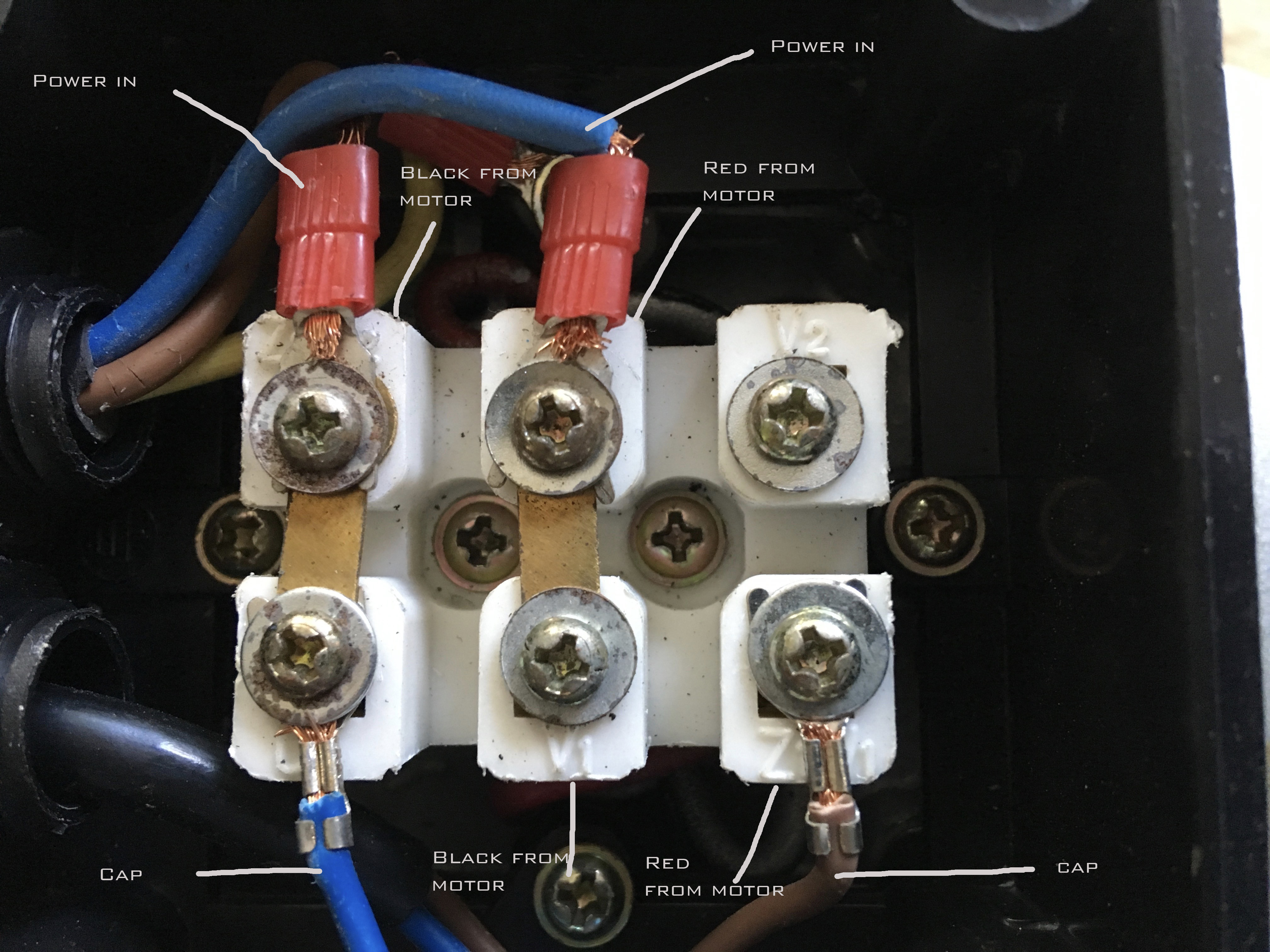
A three-phase motor must be wired based on the diagram on the faceplate. The first step is to figure out the voltage of your phases. In the United States, for low voltage motors (below 600v), you can expect either 230v or 460v. That being said, there is a wide range of different motors and what you have on hand can be completely different.

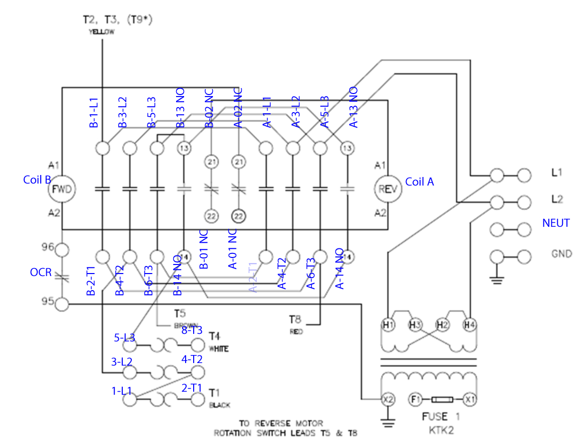
480v 3 Phase Reversing Motor Starter Wiring Diagram
Jul 09, 2021 · 3 Phase Induction Motor Diagram Pdf. Amarante Pruvost. July 9, 2021. Three Phase Induction Motor Blow Up Diagram Of Construction Parts Induction Electrolytic Capacitor Motor Works. Pin On 3 Phase Wiring. 3 Phase Forward Reverse Switch Wiring Diagram Earth Bondhon Reverse Delta Connection Switch. 36 Slots 3 Phase 6 Pole Induction Motor Rewinding ...

motor star delta connection | Delta connection, Basic ...
3 Phase Motor Connection Diagram Pdf. angelo. November 26, 2021. 3 Phase Electrical Switchboard Wiring Diagram And Phase Wiring Installation In House Electrical Wiring Diagram Electrical Wiring Electrical Circuit Diagram. Ac Blower Motor Wiring Diagram Furthermore 3 Phase Star Delta Motor Conn Instalacion Electrica Industrial Diagrama De ...

3 Phase Motor Starter Wiring Diagram Pdf — UNTPIKAPPS
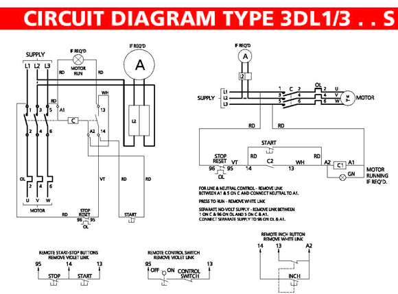
3-Phase Motor A1 A2 95 Reset L1 L2 L3 Common Control Separate Control 1/ 3/ 5/ T1 T2 T3 T1 T2 T3 96 97 98 3 2 ìC " Remote Pilot Devices 2-Wire Control 3-Wire Control Start Stop 3 2 1 1 3 Not for use with Auto Reset OL Relays. 2/ 4/ 6/ M 1 OL 3-Phase Motor A1 A2 Remove Wire "C" when it is supplied. Connect Separate Control Lines to the No ...

DOL Starter Wiring Diagram For 3 Phase Motor Controlling
PO Box 130 350Vaiden drive Hernando, MS 38632-0130 Phone: 662-429-8049 Fax: 662-429-8546 Toll Free: 800-884-0404 www.naemotors.com SINGLE PHASE MOTOR WIRING DIAGRAMS
32 3 Phase Motor Starter Wiring Diagram Pdf - Wire Diagram ...
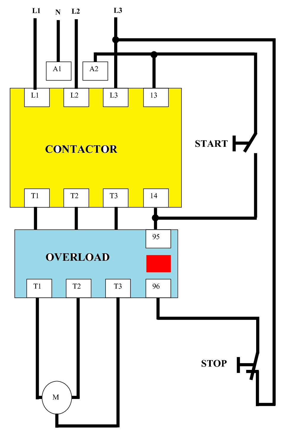
Dol Starter Wiring Diagram 3 Phase Pdf Connecting a small electrical motor to a power source via a switch or by plugging induction motor directly to the power source via a three-phase contactor. Figure 6 shows a typical DOL starter with overcurrent and overload protections.

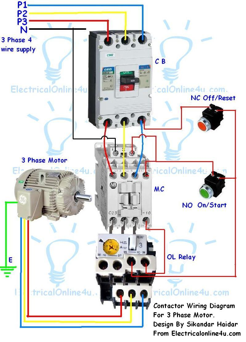
3 Phase Contactor With Overload Wiring Diagram Pdf ...
Pdf A Simple Method For Operating The Delta Connection Standard Of 3 Phase Induction Motor On Single Supply. Forward Re Verse Control Developing A Wiring Diagram And Reversing Single Phase Split Motors Electric Equipment. Choosing Capacitor When Translate 3 Phase Ac Motor Into Single Plcs Net Interactive Q A.

Wiring Diagram 3 Phase Contactor
THREE PHASE INDUCTION MOTOR 1. Flexible 5 ratings correspondence ... Lead Wire Connection 6 lead wires with Terminal block ... TOSHIBA THREE PHASE INDUCTION MOTOR TOSHIBA THREE PHASE INDUCTION MOTOR Connection Diagram Δ:220V-50/60Hz, Y:380/415/440V-50/50/60Hz (Frame size: 71M~160L) Δ:380V-50Hz, Y:660V-50Hz
32 3 Phase Motor Starter Wiring Diagram Pdf - Wire Diagram ...
• The 3-phase set of currents, each of equal magnitude and with a phase ... principle-of-three-phase-induction-motor/ Per-phase equivalent circuit • Motor Slip ... • R c: core loss resistance • Rotor winding parameters are referred to the stator side s s m n n n s Power flow diagram 3 [ (1 ) / ] 3 3 ( / ) 3 / 3 2 2 2 2 2 2 2 2 2 2 1 1 2 ...
3 Phase Motor Starter Wiring Diagram Pdf | Wiring Diagram
3 phase motor starter wiring diagram pdf - You will need a comprehensive, expert, and easy to comprehend Wiring Diagram. With this kind of an illustrative manual, you'll have the ability to troubleshoot, stop, and total your tasks without difficulty.

9 Creative 3 Phase Motor Starter Wiring Diagram Pdf Photos ...
3 phase motor starter wiring diagram pdf source. A wiring diagram is a streamlined conventional photographic representation of an electrical circuit. Ac manual starters and manual motor starting switches 12 class 2510 12 class 2511 and 2512 13 2 speed ac manual starters and. Phase 2 l1 l2 l3. They can be used as a guide when wiring the controller.
3 Phase Magnetic Motor Starter and Wire Diagram - YouTube
TWO-SPEED MOTORS For all other SINGLE-PHASE wiring diagrams refer to the manufacturers data on the motor. Diagram DD6 Diagram DD7 M 1~ LN E Diagram DD8 LN E L1 L2 L3 S/C Z1 U2 Z2 U1 Cap. Thermal contacts (TB) white M 1~ Z2 - Yellow Z1 - Blue U2 - Black U1 - Red Bridge L1 and L2 if speed controller (S/C) is not required M 1~ LN E White Brown ...

3 Phase Dol Starter Wiring Diagram Pdf - Wiring Diagram ...
TWO-SPEED MOTORS For all other SINGLE-PHASE wiring diagrams refer to the manufacturers data on the motor. Diagram DD6 Diagram DD8 M 1~ LN E Diagram DD9 M 1~ LN E White Brown Blue L1 L2 N S/C Bridge L1 and L2 if speed controller (S/C) is not required Diagram DD7 LN E L1 L2 N S/C Z2 U2 Z1 U1 Cap. Thermal contacts (TB) white M 1~ Z2 - Yellow (AUX ...

A beautiful cat.

Playstation 3 Semi-Transparent SIXAXIS Controller
Circuit Shown Direction Control | Wiring Circuit Diagram

Wiring Diagram For 230V Single Phase Motor - Collection ...

Three Phase Motor Power & Control Wiring Diagrams

Electrical Wiring Diagram Star Delta Pdf Perfect 2 Speed 3 ...

9 Creative 3 Phase Motor Starter Wiring Diagram Pdf Photos ...

Single Phase Motor Forward Reverse Wiring Diagram Pdf ...

3 Phase Motor Starter Wiring Diagram Pdf | Wiring Diagram
Basic steps in PLC programming for beginners | EEP

3 Phase Motor Wiring Diagram Pdf - Atkinsjewelry
Single phase motor wiring help - Machinery General ...

Scooter, Perseverance, success, motivation, the end

Electrical Wiring Diagram Star Delta Pdf Perfect Wiring ...

32 3 Phase Motor Starter Wiring Diagram Pdf - Wire Diagram ...

Tesla Model 3 interior

TYPICAL WIRING DIAGRAMS SIEMENS

3 Phase Motor Starter Wiring Diagram Pdf — UNTPIKAPPS

3 Phase Motor Starter Wiring Diagram Pdf — UNTPIKAPPS

Three Phase Geared Motors 750 Rpm | Electrical Winding ...

Motor Starter Wiring Diagram Start Stop Top Weg Wiring ...

the one and only Saigon

Scooter, Perseverance, success, motivation, the end, search
Star Delta Starting - YouTube

3 Phase Motor Wiring Diagram Pdf

Wiring Diagram Single Phase Motor Contactor - Wiring Forums
![[XL_8743] Wiring Diagram For Contactors Wiring Diagram](https://static-resources.imageservice.cloud/204920/3-phase-contactor-wiring-wiring-diagrams.jpg)
[XL_8743] Wiring Diagram For Contactors Wiring Diagram
3 Phase Motor Starter Wiring Diagram Pdf Download - Wiring ...

3 Phase Wiring Diagram Critique

Dol Starter Wiring Diagram 3 Phase Pdf
0 Response to "44 3 phase motor wiring diagram pdf"
Post a Comment