41 electric temperature gauge wiring diagram
7. Connectone end of another length of 18-gauge insulated copper wire to the center connection post, as shown in Diagram 2 and the other end of the wire to a good ground source. 8. Connect a third length of 18-gauge insulated copper wire to the right connection post as shown in Diagram 2, and the other end of the wire should be connected to the ... instructions for the installation of the electric temperature, pressure and/or fuel gauge are contained herein. use is restricted to 12-volt negative ground electrical systems. light bulb, if supplied, is 12 volt. ˘ ˇ ˇ ˆ¹⁄₁₆ ˆ ⁵⁄₈ ˙ ˝ ˛ ˚ ˜ ˜ ˘ ! "!
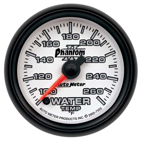
The Equus 6000 Replacement Instrument Series single 2 in. electrical temperature gauge console offers excellent instrumentation value featuring easy to read 90 degree sweep white on black dial artwork with high contrast orange needle, through dial backlighting, and electrical movement for efficient monitoring of your engine coolant / water temperature.
Electric temperature gauge wiring diagram
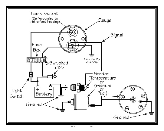
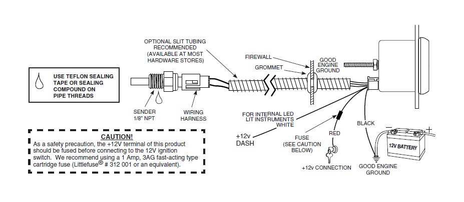
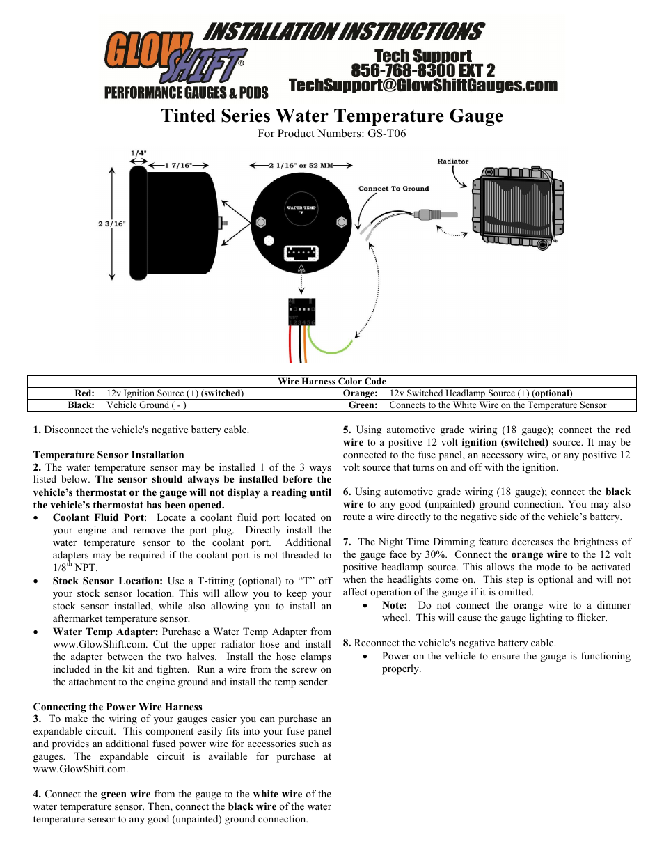
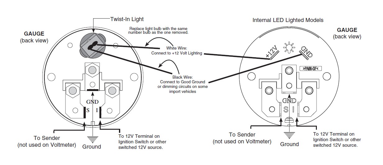
5. detected, Determine the cause of the leak and repair. Connect the white wire to dash lighting or switchable 12v light source, the red wire to switched +12V source and the black wire to ground.(see diagram for details) 6. Install temperature sender. Water Temp: Install temperature sender. 1/8" NPT. For 3/8" NPT or 1 " Aug 15, · Autometer Pyrometer Wiring Diagram auto meter ficial site trade in any aftermarket gauges for credit on new autometer gauges 15 trade in trade up read more auto Autometer Pyrometer Wiring Diagram Isspro Electric Water Temp img source: diagramweb.net Autometer Pyrometer Wiring Diagram As Well As Temperature Gauge img source. Connect one wire from the gauge light to a grounded metal part of the vehicle chassis using an existing bolt or self-tapping screw. Connect the other wire to a positive (+) 12 volt wire from the dashboard lighting circuit using a wire tap-splice. Clip the gauge light into the hole in the back of the temperature gauge.
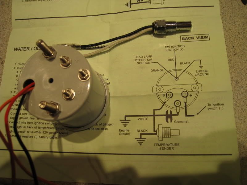
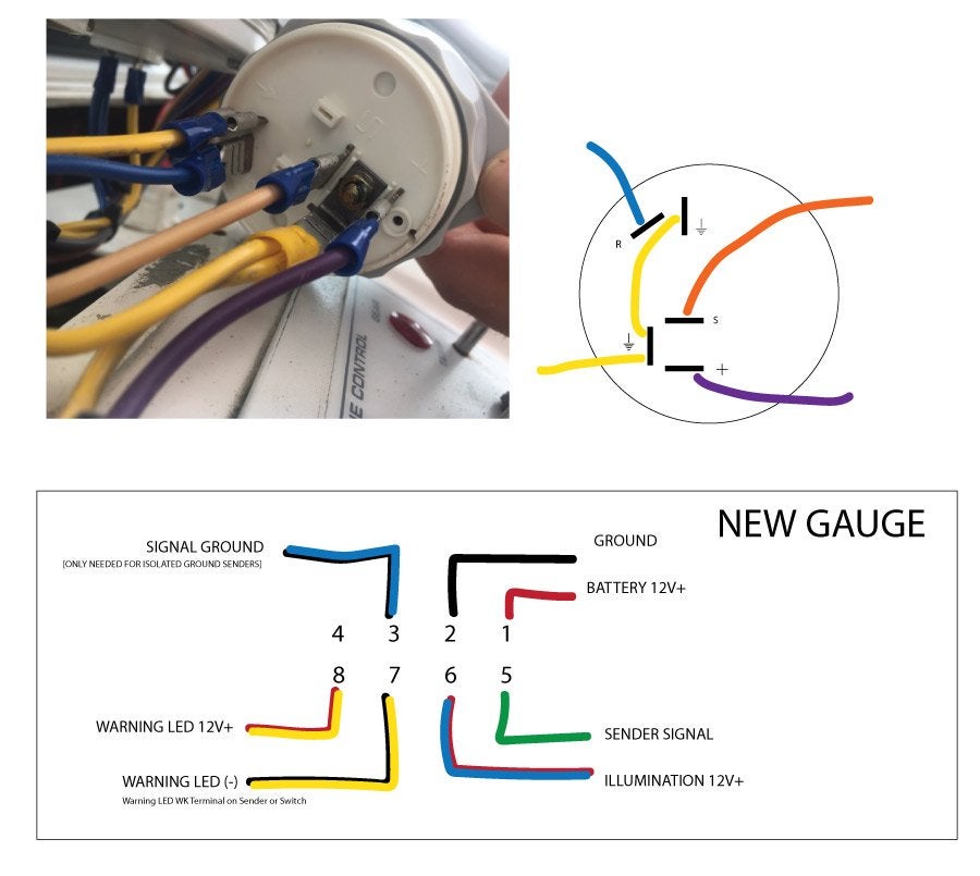
Electric temperature gauge wiring diagram. Smiths Electric Oil Pressure Gauge From Competition Supplies Worldwide Shipping Available. Smiths temp gauge wiring problems instructions for 52mm electrical gauges temperature classic smith fuel goes by rev voltage ilizers revised electric oil morgan 4 8 aero car reading affecting tank and water morris minor owners club question bt2240 01c e type ammeter pressure how to install an bf6108 00b ... Temperature Gauge Wiring Diagram - wiring diagram is a simplified all right pictorial representation of an electrical circuit. It shows the components of the circuit as simplified shapes, and the aptitude and signal associates amid the devices. 4. Run a length of 18-gauge insulated copper wire from the gauge's mounting location to the sender's mounting location. 5. Attach the 18-gauge wire onto the top of the gauge's sender. 6. Facing the back of the gauge, the connection post on the right is for the +12-volt power, the center post is for the ground connection and the Smiths water temperature gauge wiring diagram. 2500f1200c water temperature gauge use with vdo sender 12v 250 spade connection learn more cockpit international 1200c water temperature gauge use with vdo sender 24v 250 spade connection. Engine temperature directly affects combustion and moving internal parts.
Jan 10, 2018 · 5. Wiring diagrams VDO cockpit international (for engine coolant) The electrical oil temperature gauge has been designed for land-bound vehicles or.THE INSTRUCTIONS FOR INSTALLATION AND ELECTRICAL WIRING FOR THE INSTRUMENT KIT FOLLOWS. USE IS RESTRICTED TO 12 VOLT NEGATIVE GROUND ELECTRICAL SYSTEMS. Temperature Gauge (21/16" diameter) 1 6. Wire minimum with an insulation temperature rating of 220 f 105 c minimum from the battery terminal on the starter solenoid to the right terminal on the ammeter see wiring diagram. Also known as an ammeter this is one of the instruments that has largely been replaced with an idiot light. 2 classic instruments amp gauge should only be used on ... Gauges. Morgan 4 8 Aero Car Wiring Diagrams Spares Com. 1 2 3 Wire Coolant Temperature Sensor Wiring Diagram Master In Min. Temperature gauge new vdo temp wiring troubleshooting boat gauges derale 2 inch 52mm digital car red led installation instructions basic water sensor transmission circuit diagram performance instruments smiths problems ing ... 22.03.2019 22.03.2019 6 Comments on Autometer Water Temp Gauge Wiring Using 18 gauge wire route one length through firewall using See other side for Pressure & Temperature Gauges, and Service/Warranty information.
Trans Temp Gauge Installation: but an A-pillar gauge mount is available as a professional location to mount two gauges. diagramweb.net has a 2 & 3 gauge pod available Pictured below is a copy of the wiring diagram for the Autometer Transmission Temperature Gauge. STEP 4. NOTE: Wire for gauge lights must be purchased separately. Use size 18-20 AWG stranded copper wire. 2. Splice the RED or WHITE wire from the gauge light(s) into the vehicle's lighting circuit, between the dimmer control switch and the dash lights (consult the vehi-cle's service manual for proper wire). 3 GAUGE LIGHT INSTALLATION AND CONNECTION3. Auto Gauge Tach Wiring – Wiring Diagram Data – Autometer Gauge Wiring Diagram Wiring Diagram consists of numerous in depth illustrations that show the connection of varied items. It contains directions and diagrams for various varieties of wiring strategies along with other things like lights, windows, etc. DARK GREEN Temperature Gauge (-) sender Use terminal J and connector K. See diagram. This kit is designed to be used with an electric 1956 gauge. If using a stock 1955 gauge, discard this wire and use the capillary tube on your gauge. Otherwise, use a 1956 electric gauge. DARK BLUE Oil Pressure Gauge
Autometer Oil Pressure Gauge Wiring Shortcut? - General ...
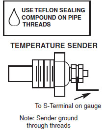
SHORT SWEEP ELECTRIC GAUGES 2650-1079-00 Rev. C Mounting ... Temperature Gauges TEMPERATURE SENDER USE TEFLON SEALING COMPOUND ON PIPE 1. Install temperature sender. THREADS ... nuts on back of gauge. +-Wiring Read before installing: Must be installed by experienced technician.
Electric Temperature Gauge Wiring Diagram - Wiring Diagram
There are a several checks you can perform to verify the gauges in your instrument cluster are working correctly. These can be helpful if you're trying to de...

Vw Bug Vdo Electronic Speedo Wiring Diagram
I want to wire two separate switches (both on the same circuit) in a 2 gang box. One will control 4 can lights, and the other will control 3 can lights. This is in my basement. The power will be feeding the switch box first. Hope this is clear. Any help or a diagram would be very helpful!
Temperature Gauge Wiring Diagram - Complete Wiring Schemas
Instruction Manual. driving. Also check behind the mounting location for any wiring or components before drilling. Fig 1. Gauge Wiring Diagram. Table 1. Wiring Summary. Color. RACETECH-LOGO-GREEN The Racetech electrical water temperature gauge is manufactured specifically for competition use having Instruction Manual.
Gauges
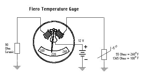
Engine temperature directly affects combustion and moving internal parts. Without a temperature gauge, the engine would be subject to various modes of heat without the operator's knowledge, and this could lead to bearing failure and engine seizure. A vehicle owner can wire a temperature gauge in his or her vehicle in a driveway or garage.
GlowShift Water Temperature Gauge User Manual | 2 pages
Vdo water temperature gauge wiring diagram. I installed the vdo oil pressure and temperature gauges in my 1970 vw but will give you the concept on installing them in any vehicle. Coolant temperature oil temperature oil pressure fuel level and speed. All in one digital display system. This is part 1 on how to install vdo gauges.

Vdo Electronic Speedometer Wiring Diagram
4.Choose a wire size from the table in Diagram 6 that is a large enough gauge (larger size wire has a smaller gauge number) to handle the maximum rated output of your vehicle alternator/gener - ator. Obtain two lengths of this size wire, each long enough to go from the location chosen in Step 2, to the ammeter mount - ing location at the dashboard.
How to Install Auto Meter Sport Comp II Transmission Temp ...
1964-1978 mgb electrical wiring diagrams pdf updated: december 2021 ... wb lg/b g g n n regulator ignition coil n distributor wr + gu - w lg/g wb fuse box - + starter temp gauge & sender gauge voltage stabilizer g b i g w g w 1 b wn lg/g oil pressure gage & sender 2 w lg/g batteries b gb n 3 n headlight switch n 3 4 4 g 1 4 3 fuel gauge ...

Vdo Temperature Gauge Wiring Diagram/
Diagram G Wiring Diagram WIRING OF POWER AND GROUND TO EACH GAUGE ILLUMINATION WIRING . °F/°C Water Temperature Gauge, Use with VDO Sender, 12V," Spade Connection Learn More ViewLine Ivory °F/°C Water Temperature Gauge 12/24V & . VDO Water Temp Gauge See more like this. VDO Cockpit Electrical Water Temperature Gauge 2 1/16" Dia Black Face ...
Autometer Water Temp Gauge Wiring
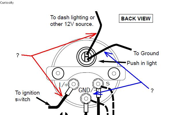
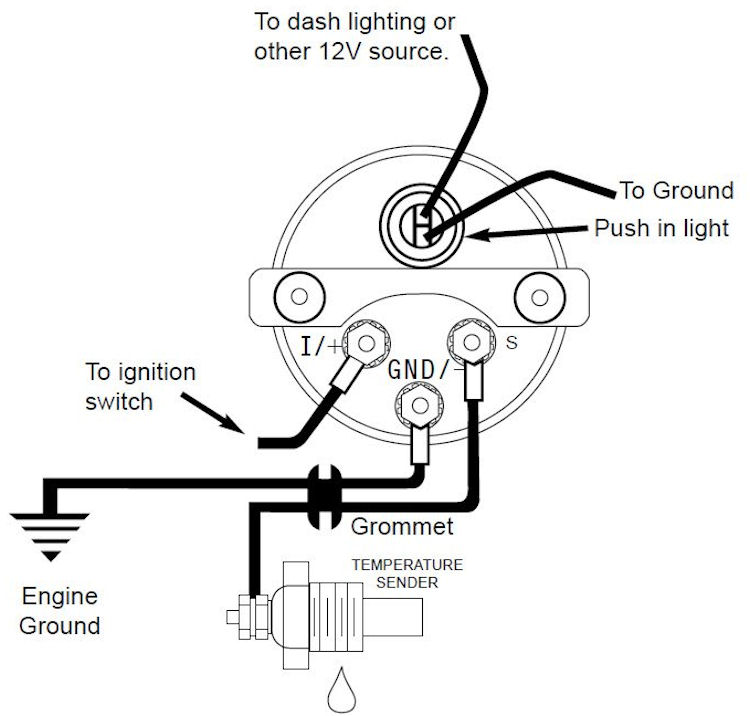
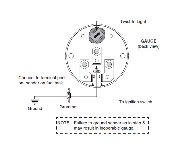
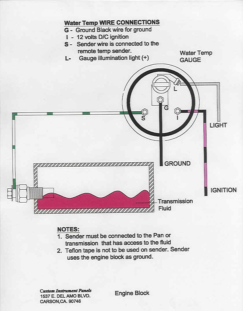
TEMPERATURE GAUGE WIRING (Figure 3): 1. Disconnect negative (-) battery cable. 2. Using 18-ga. wire, connect the (G) terminal to a clean (rust/paint-free) ground surface near the temperature sender. 3. Using 18-ga. wire, connect the (I) terminal to a switched +12V source. 4. Using 18-ga. wire, connect the (S) sender terminal of the

Mother taking the temperature of her daughter with an ear thermometer
1 IS 300 ELECTRICAL WIRING DIAGRAM 1 P 1 1 1 1 2 1D 1 1O 2 ACC IG1 IG2 ST2 AM1 4 6 8 7AM2 8 EA1 IH Cowl side panel RH 1 11 4 1D 7. 5A STARTER 81K 2 EA1 6EA1 1 B 1A 3EA1 5 1K 5 1D 1A B 1 B 2 B 3 B L IG S 9EA1 1 1D F 10A GAUGE 91K D B A 26 F 27 C See Multiplex Communication System<10-4> Power Source Starting and Ignition Charging 121 2 2 9 212 ...
How to Install an Auto Meter Pro-Comp Ultra-Lite Water ...
Electric temperature gauge wiring diagram. We features pre made electrical wiring representation themes. Vdo water temp gauge see more like this. Wire connect the i terminal to a switched 12v source. Temperature gauge wiring figure 3. Short sweep electric gauges 2650 1079 00 rev. Must be installed by experienced technician.
Autometer Water Temp Gauge Wiring
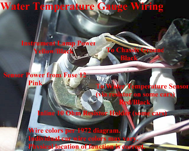
Connect one wire from the gauge light to a grounded metal part of the vehicle chassis using an existing bolt or self-tapping screw. Connect the other wire to a positive (+) 12 volt wire from the dashboard lighting circuit using a wire tap-splice. Clip the gauge light into the hole in the back of the temperature gauge.

Engine Temperature Gauge Wiring Diagram - Wiring Forums
Aug 15, · Autometer Pyrometer Wiring Diagram auto meter ficial site trade in any aftermarket gauges for credit on new autometer gauges 15 trade in trade up read more auto Autometer Pyrometer Wiring Diagram Isspro Electric Water Temp img source: diagramweb.net Autometer Pyrometer Wiring Diagram As Well As Temperature Gauge img source.

Wiring Diagram For Temp Gauge - Wiring Diagram Schemas
5. detected, Determine the cause of the leak and repair. Connect the white wire to dash lighting or switchable 12v light source, the red wire to switched +12V source and the black wire to ground.(see diagram for details) 6. Install temperature sender. Water Temp: Install temperature sender. 1/8" NPT. For 3/8" NPT or 1 "
Wiring Diagram For Temp Gauge - Wiring Diagram Schemas

Engine Temperature Gauge Wiring Diagram - Wiring Forums

1994 Chevrolet Truck S10 Blazer 4WD 4.3L FI OHV 6cyl ...

Wiring Diagram For Vdo Oil Pressure Gauge

Glowshift Trans Temp Gauge Wiring Diagram

Vdo Oil Pressure Gauge Wiring Diagram Blue - Complete ...

1987 Ford F 150 Wiring Diagram Ecu - Wiring Diagram Schema
HOW TO:dual fuel pump & aftermarket gauges install - Club ...

Sunpro CP7005 Sport ST 2 Electrical WaterOil Temperature ...
Electrical Diagrams
Autometer Water Temp Gauge Wiring

TAKE IT IN TOP!: Wiring Diagram for Smiths Classic Gauges
Electric Temperature Gauge Wiring Diagram - Wiring Diagram

Vdo Oil Pressure Gauge Wiring Diagram Blue - Complete ...

Temperature Gauge Wiring Diagram - Wiring Diagram And ...
How to Install Auto Meter Sport Comp II Transmission Temp ...
wiring diagram for temp gauge sensor... - Pennock's Fiero ...

Gretsch Guitar

30 Autometer Pyrometer Wiring Diagram - Wiring Diagram ...
Vdo Rev Counter Wiring Diagram

Free Auto Wiring Diagram: 2000 Ford Explorer Temperature ...

Autometer Gauge Wiring Diagram Short Sweep
Autometer Tachometer Wiring Diagram
Engine Gauge Wiring Diagram - See also Gauge Testing ...

Autometer Trans Temp Gauge Wiring Diagram

fitting water temperature Gauges
0 Response to "41 electric temperature gauge wiring diagram"
Post a Comment