45 fire alarm horn strobe wiring diagram
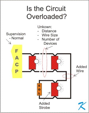
Jul 22, 2020 · Fire Alarm Strobe Wiring Diagram | Manual E-Books – Fire Alarm Horn Strobe Wiring Diagram Wiring Diagram contains several detailed illustrations that display the link of varied products. It includes directions and diagrams for various varieties of wiring methods as well as other items like lights, home windows, and so on. FIRE ALARM SECURITY ACCESS CONTROL CCTV ... Wiring diagrams provided herein are for information and reference only and are not to be used for installation purposes. Consult the appropriate installation ... Integrity: Horns, Horn-strobes: 757 Series 54 Hazardous Location Notification Appliances 55.
Fire Alarm Horn Strobe Wiring Diagram. Best Of- Allowed to my own website, within this period I am going to explain to you in relation to fire alarm horn strobe wiring diagram. . And today, this is the 1st picture: Fire Alarm Horn Strobe Wiring Diagram Image from fire alarm horn strobe wiring diagram , source:magnusrosen.net.
Fire alarm horn strobe wiring diagram
wg = wire guard h = high audible setting l = low audible setting c = ceiling mount ... p = pendent sl = signal light ri = remote indicator horn only c = ceiling mount speaker only c = ceiling mount bell - single stroke bell - trouble gong visible only (strobe) - wall mount ... fa-107 level 7 fire alarm floor plan. 15 60 15 30 15 15 60 75 75 15 ... Fire Alarm Horn Strobe Wiring Diagram – fire alarm horn strobe wiring diagram, Every electric structure is composed of various different parts. Each component should be placed and connected with other parts in specific manner. Otherwise, the arrangement will not work as it should be. 3. see plans for location and quantities of fire alarm devices. all horn and strobes shall be wired on alternate circuits. 4. all wiring to fire alarm devices shall be teflon coated approved for fire alarm system. run #14awg minimum exposed in accessible ceiling area. otherwise run in 3/4" emt conduit. 5.
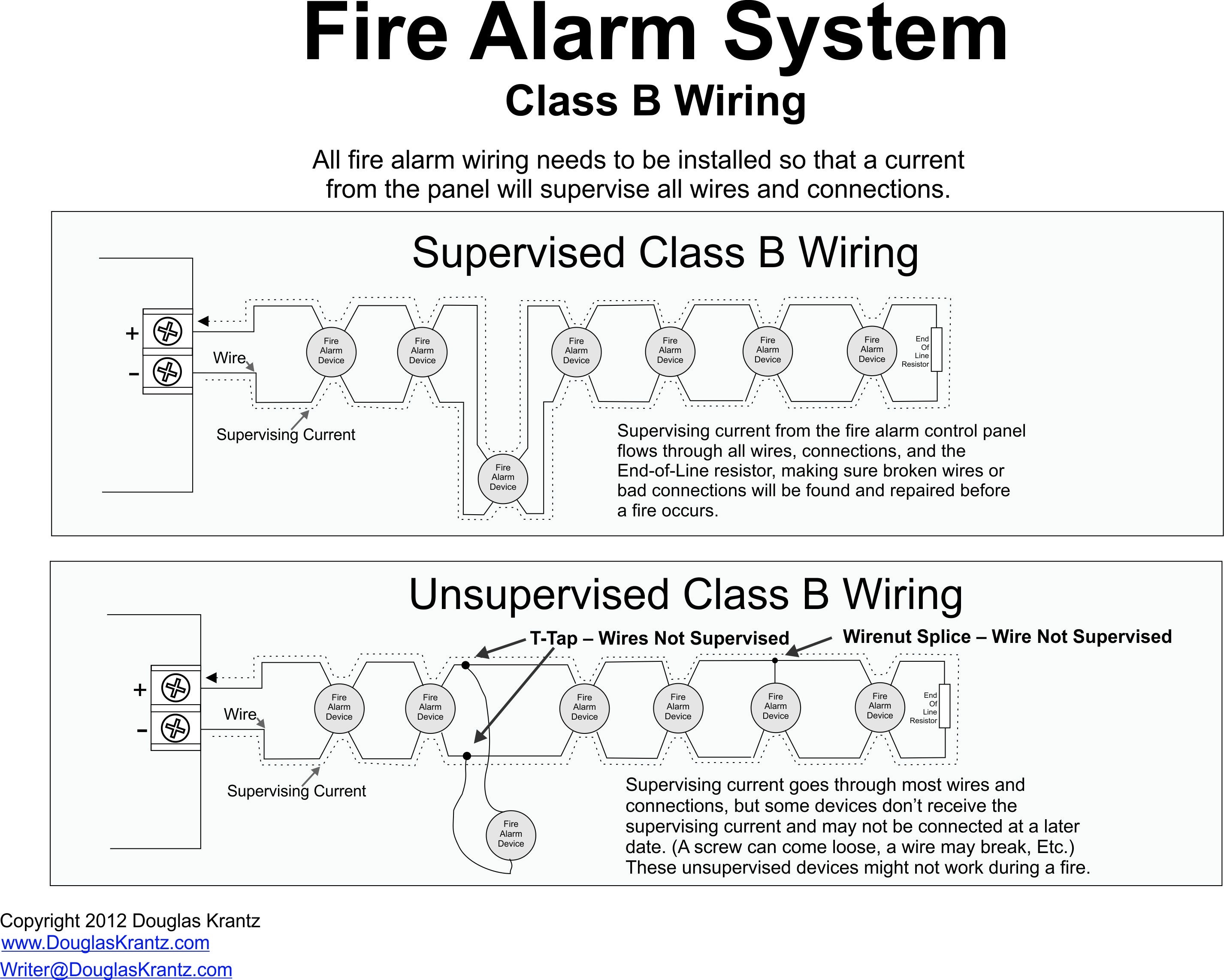
Fire alarm horn strobe wiring diagram. The HS-24WR is a low profile horn/strobe combination that offers dependable audible and visual alarms and the absolute lowest current available. The HS-24WR 24VDC offers tamperproof field selectable candela options of 15, 30, 60, 75, and 110 candela. The Horn/Strobe offers a continuous or sync temporal three in 2400Hz and mechanical tone, a Assortment of fire alarm horn strobe wiring diagram. Fire alarm wiring diagram. It reveals the elements of the circuit as simplified shapes and the power and signal links in between the tools. A wiring diagram is a streamlined standard pictorial representation of an electric circuit. Otherwise the arrangement will not work as it should be. connection of alarm transmission wiring, communications, signaling, and/or power. If detectors are not so located, a developing fire may damage the alarm system, compromising its ability to report a fire. Audible warning devices such as bells, horns, strobes, speakers and displays may not alert people if these devices are fire alarm horn strobe wiring diagram - What's Wiring Diagram? A wiring diagram is a form of schematic which uses abstract pictorial symbols to exhibit every one of the interconnections of components in a system.
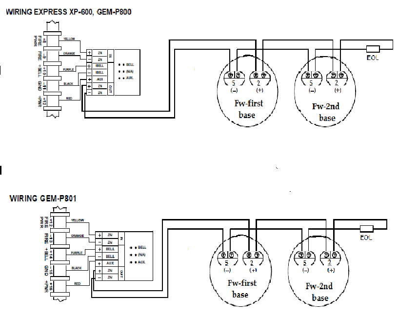
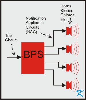
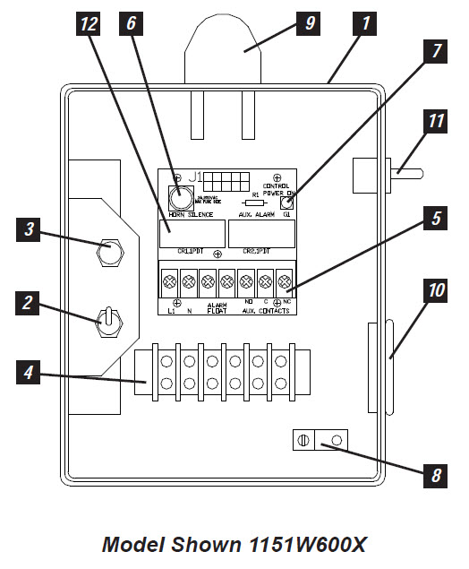
The Simplex model number checker can be found in the following link, but remember that ONLY Simplex devices are affected by this, almost any other alarm will... Types Notification Appliance Circuits/Control Circuits (NAC) Supervised polarity reversing power circuits for Horns, Strobes, Bells, Chimes Any NAC that does not have a Notification Appliance attached shall be considered a Control Circuit Performance shall be based upon wiring Class (Note the old Class & Style has been replaced with Class only) DF-51609 — Page 5 of 6 WIRING DIAGRAMS NOTE: Do NOT loop wires under terminal screws. Tandem Operation Independent Operation Horns silenced over two-wire circuit. • Any mix of horn/strobes or strobe-only devices is acceptable. • Horn control connects to interruptible power source. Fire Alarms Explained is a series where Zach discusses basic concepts of fire alarm systems, as well as showing the specific systems hands on. This is a new ...
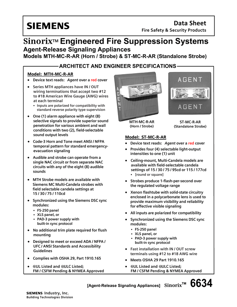
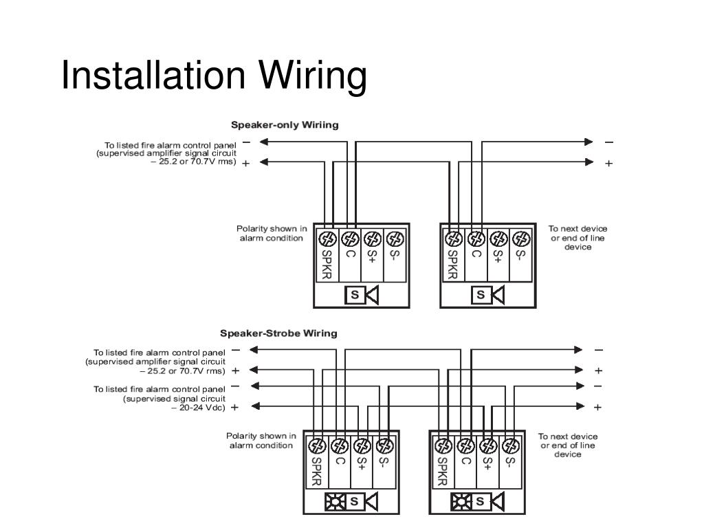
ible with the previous generation of SpectrAlert notification appliances. Horn/ strobe products are available in two versions. The 2-wire products fit systems where a single NAC controls both horn and strobe. The 4-wire products are in - tended for systems which have separate wiring circuits for the horn and strobe. Jul 23, 2020 · Fire Alarm Strobe Wiring Diagram | Manual E-Books – Fire Alarm Horn Strobe Wiring Diagram Wiring Diagram contains several detailed illustrations that display the link of varied products. It includes directions and diagrams for various varieties of wiring methods as well as other items like lights, home windows, and so on. FIRE ALARM SySTEM CONSIDERATIONS All wiring must be installed in compliance with CSA C22.1 Canadian Electri-cal Code and applicable local codes. System Sensor recommends installing fire alarm speakers in compliance with CAN/ULC S524. Also refer to fire alarm panel installation instructions to determine suitable wire gauge to be 2. all fire alarm installations, including pulling of wire and mounting of devices, shall have oversight of a nicet level ii fire alarm technician or higher. 3. strobes in common view shall be synchronized by circuit. 4. all fire alarm/mns cable shall be run in red factory colored conduit. 5. these design documents provide general spacing ...
Fire Alarm Horn Strobe Wiring Diagram Gallery. fire alarm horn strobe wiring diagram - Building circuitry diagrams show the approximate locations and also affiliations of receptacles, lights, as well as irreversible electrical services in a building. Interconnecting cable courses might be revealed roughly, where specific receptacles or fixtures should get on a common circuit.

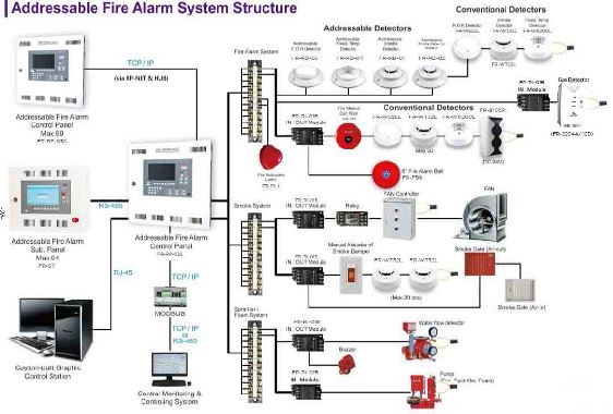
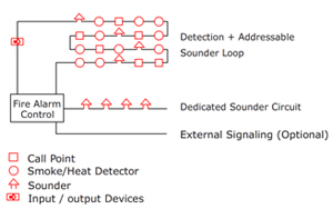
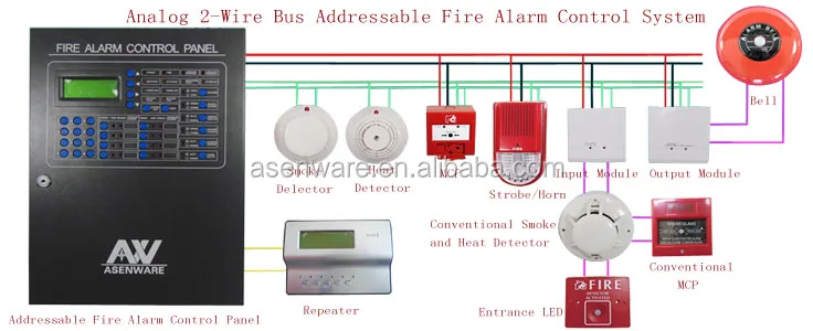
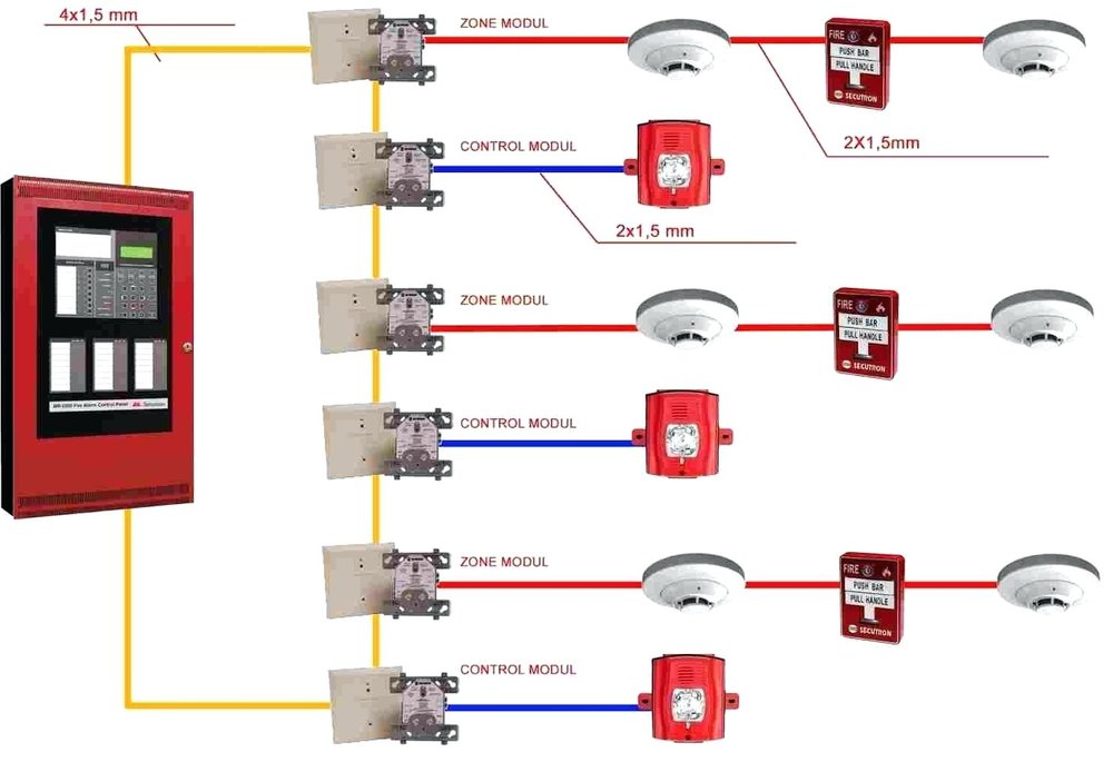
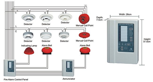
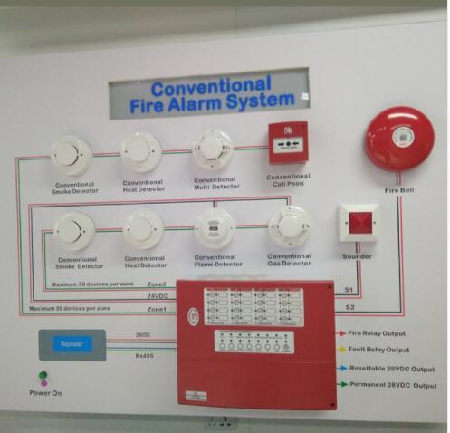
Indicating Appliance Circuits connect the fire alarm panel to the components which alert building occupants of the fire, i.e., bells, horns, speakers, strobe lights, etc. The following illustrations show schematics, wiring connections, riser diagram, and wire pull, for some commonly used fire alarm circuits.

Is this an addressable 4 wire speaker strobe china ul listed fire alarm system wall ceiling mounted for indoor use applications dt981w dt982w horn cft 991 professional conventional and intelligent alarms why won t the added horns strobes work call us 01067960999 01002378587 logo contact time sat thu 9 am pm phone number mail deltafire45 yahoo com navigation… Read More »
Autowatch 446 Wiring Diagram Manualzz. Bmw alarm wiring help tdiclub forums wire it to my driveway using siren output relay diagram how simon xt drive honeywell home outdoor can i a or strobe connect car horn dsc security system burglar 180072 harness f355 n 2 gemini manualzz installation diagrams remote starter external ge mongoose m60 install problem accenta g4 break sensor circuit schematic ...

by the fire alarm control panel, ensuring device disconnections or failures are quickly detected and reported. Addressability also allows key properties like the device candela rating and tone pattern to be set right from the fire alarm panel. With TrueAlert ES we have also changed the way we power and wire the notification appliances.
Select-A-Strobe. the strobes remain flashing, Refer to the wiring diagram Fig.1 yr dBA refer to Table 1. The Genesis Temporal Horn-Strobe is a fire alarm notification The strobe includes a field-configurable switch for selecting the Figure 3: Wiring diagram. 1. 2. vices can be activated by a compatible fire alarm control panel or power sup- ply.
horn/strobe control or with TrueAlert addressable control; for horn/strobe appliance applications, use 4-wire appliances (see data sheet S4903-0011), for horn control, select horn operation as free-run Wire Connections Screw terminals for in/out wiring, 18 to 12 AWG wire (0.82 mm2 to 3.31 mm2)
vices can be activated by a compatible fire alarm control panel or power sup - ply. Refer to the appropriate fire alarm control panel manufacturer or power supply for more information. System Sensor wall 4-wire horn strobes are electrically backward compat-ible with the previous generation, since 1996, of notification appliances.
The fire alarm authority. Strobe light wiring diagram wiring diagram for flashing lights new wiring diagram for relay for spotlights new how to wire. Ford f 150 lariat wiring harness diagram 2018 pictures. For permanent installations be sure to solder your wires or use weath. 1965 ford mustang wiring diagram pdf database. Assortment of strobe ...
Fire Safety Signaling Devices Are Covered Under Title III The ADA comprises four titles that define and prohibit discrimination on the basis of disabilities within specific areas. Fire safety signaling devices are addressed under Title III, which covers public accommodations and services, including transportation. Compliance is enforced by the

Fire Alarm Horn Strobe Wiring Diagram Circuit Diagram Addressable Fire Alarm System Wiring Pdf. Find this Pin and more on Fire alarm system by Jsimba Mitcham. Demogorgon Stranger Things. Structured Wiring. Lighting Control System. Engineering Works. Fire Alarm System. Diagram Design.
All horn and strobes shall be wired on alternate circuits. If no FIRE occurs the thermistor will remain at 10 K. Simple Fire Alarm Circuit Using Thermistor Germanium Diode And Lm341 Fire Alarm Circuit Diagram Circuit Install an alarm bell back box and the fire to my house is bells installation sheet automatic alram circuit […]
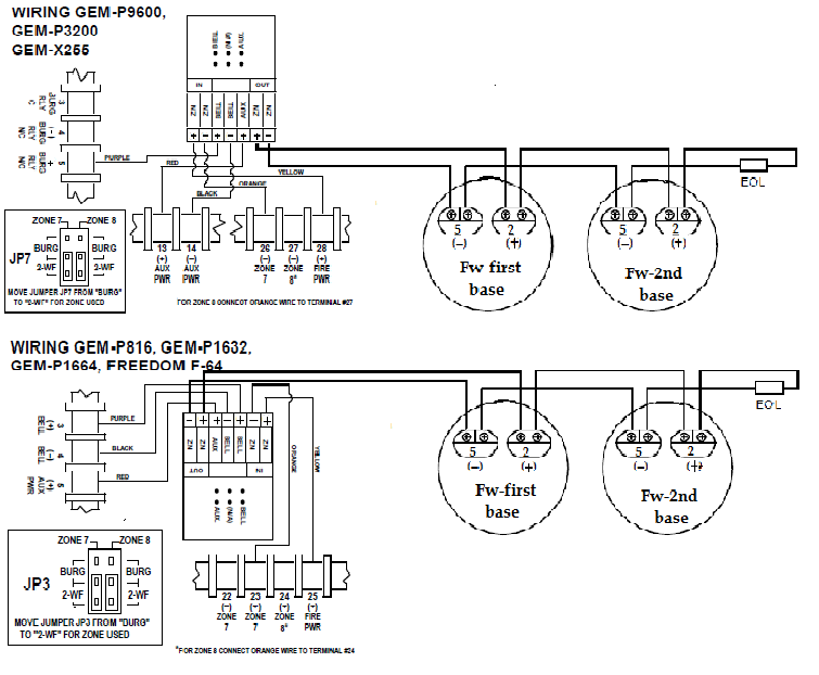
IV. WIRING Wiring for synchronized strobes and horns. Using this method you may: w Use only two wires to synchronize the temporal horn and strobe with the ability to mute the horn (place switches 1and 2in the ON position on the GEC3-12). w Mute the horn only when the temporal horn option has been selected. w Use the Gentex synchronization protocol to provide synchronization and mute the horn ...

Fire Alarm Horn Strobe Wiring Diagram. Assortment of fire alarm horn strobe wiring diagram. A wiring diagram is a streamlined standard pictorial representation of an electric circuit. It reveals the elements of the circuit as simplified shapes, and the power and signal links in between the tools. A wiring diagram generally provides information about the loved…
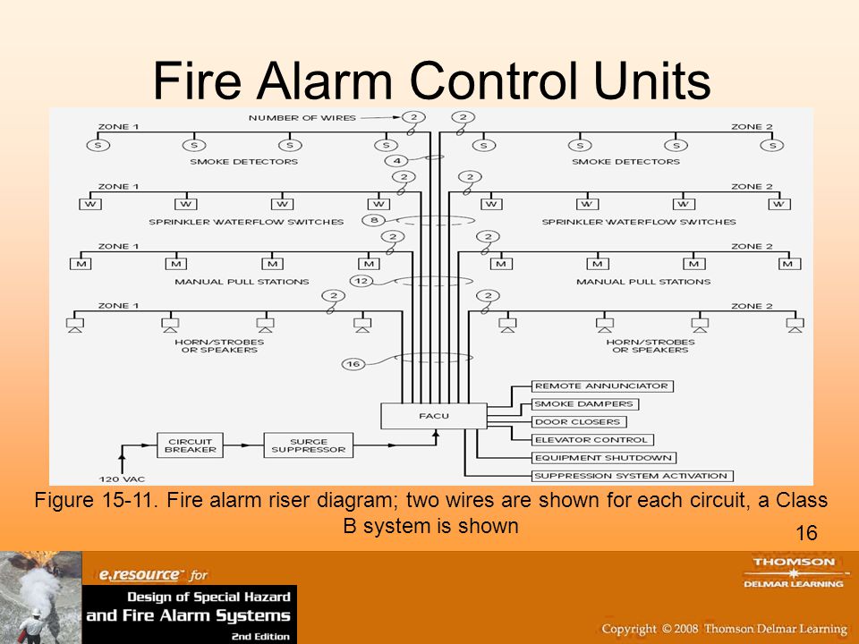
fa fire alarm matrix and riser diagram project location map scale: n/a 8001 cinder bed road, lorton, va newington fire alarm system replacement ... system smoke/heat detectors, duct detectors, horn and strobes for occupant notification, wiring, conduit and all other associated labor, equipment and materials, ... all wiring and circuits shall be ...

3. see plans for location and quantities of fire alarm devices. all horn and strobes shall be wired on alternate circuits. 4. all wiring to fire alarm devices shall be teflon coated approved for fire alarm system. run #14awg minimum exposed in accessible ceiling area. otherwise run in 3/4" emt conduit. 5.
Fire Alarm Horn Strobe Wiring Diagram – fire alarm horn strobe wiring diagram, Every electric structure is composed of various different parts. Each component should be placed and connected with other parts in specific manner. Otherwise, the arrangement will not work as it should be.
wg = wire guard h = high audible setting l = low audible setting c = ceiling mount ... p = pendent sl = signal light ri = remote indicator horn only c = ceiling mount speaker only c = ceiling mount bell - single stroke bell - trouble gong visible only (strobe) - wall mount ... fa-107 level 7 fire alarm floor plan. 15 60 15 30 15 15 60 75 75 15 ...


0 Response to "45 fire alarm horn strobe wiring diagram"
Post a Comment