42 intermatic photocell wiring diagram
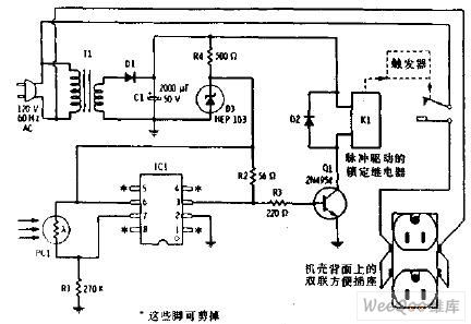
92e92Z 3 way switch wiring 4p Contactor 30a Wiring Diagram from tork wiring schematic for lighting contactor and photocell , source:diagram-vorm.stefanoandreucci.it SN 2694] cell Wiring Diagram Intermatic Time Clock from tork wiring schematic for lighting contactor and photocell , source:pila.rect.gho.kesian.illuminateatx Digital Timer Circuit Diagram. An intermatic timer switch saves electricity when it turns a water heater off at night and when it limits the amount of. Leviton timer wiring diagram another image. The on delay timer diagram is also shown in the diagram. Timer and contactor wiring diagram. The design of the timer switch is very simple.
wire guard unless noted otherwise underground transformer weatherproof cb circuit breaker above counter ground fault interrupter not in contract ground (equipment) mount or mounted empty conduit ht. ac nl mounting height night light mtd gfi nf nic h.d f g ec ex nonfused heavy duty fuse existing xfmr uno(u.n.o.) st (s.t.) so (s.o.) uf wg wp ug ...

Intermatic photocell wiring diagram
Photocell Wiring Diagram. November 21, 2021 by Rhonda Jones. A wiring diagram is an ordinary pictorial depiction of a intricate electrical circuit. This kind of diagramming is usually made in a range of layouts, including electric diagrams, WIFI-style diagrams, power supply diagrams, as well as wiring table diagrams. Categories Uncategorized Tags gate photocell wiring diagram, intermatic photocell wiring diagram, photocell circuit diagram, photocell circuit diagram pdf, photocell electrical diagram, photocell wiring diagram, photocell wiring diagram pdf, photocell wiring diagram uk, photocell wiring diagram with contactor, tork photocell wiring diagram Intermatic Photocell Wiring Diagram. Photocell Sensor Wiring Diagram Wiring Diagram Photocell Wiring Diagram Wiring Diagram consists of many in depth illustrations that present the relationship of various products. Refer to the wiring diagrams below and choose the appropriate.
Intermatic photocell wiring diagram. Categories Uncategorized Tags gate photocell wiring diagram, intermatic photocell wiring diagram, photocell circuit diagram, photocell circuit diagram pdf, photocell electrical diagram, photocell wiring diagram, photocell wiring diagram pdf, photocell wiring diagram uk, photocell wiring diagram with contactor, tork photocell wiring diagram Categories Uncategorized Tags gate photocell wiring diagram, intermatic photocell wiring diagram, photocell circuit diagram, photocell circuit diagram pdf, photocell electrical diagram, photocell wiring diagram, photocell wiring diagram pdf, photocell wiring diagram uk, photocell wiring diagram with contactor, tork photocell wiring diagram 39 2006 isuzu npr wiring diagram; 39 venn diagram generator excel; 41 how to create a venn diagram on google docs; 40 label the diagram according to the components a... 38 p28 ecu pinout diagram; 40 trane xe80 parts diagram; 40 intermatic photocell wiring diagram; 41 circle o is shown below. the diagram is not dra... 37 pbs 3 wiring diagram; 40 ... The Wiring Connections For A Pilot Light Switch So You Can See It in the Dark or When Its On Most pilot light switches require the power source to be at the switch box, such as your application. Intermatic 240v Timer Wiring Diagram - Collections Of Intermatic Pool Timer Wiring Diagram Wiring.
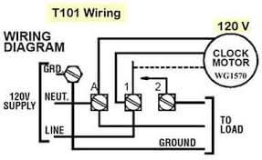
Street Light Photocell Wiring Diagram. Lighting contactors are relay switches that control the flow of electricity through a circuit powering the lighting. 3 Pole Lighting Contactor Wiring Diagram. Intermatic Photocell Wiring Diagram. Break your circuit L N E through your contactor. Intermatic T104-20 Manual such wiring diagram intermatic INTERMATIC T104 WIRING INSTRUCTIONS. How to wire Intermatic T104 and T103 and Diagram circuit clock timer wiring intermatic pool pump t101m t104m t104 instructions t104p photocell t101r t101p3 t103 240v st01 digital JennyLares Wiring Diagram Sheets Detail. 208 volt photocell wiring diagram wire a photo cell into fixture 9 full for outdoor photoelectric switch ropho get intermatic timer 6 50 3 phase motor tanning bed 240 receptacle version 120 single 220 lcs 624a 24 ac 24vac spst stem untitled snr 100w gate resources light control dc 12v 24v 220v piece lighting dusk ... Intermatic 208V Photocell Wiring Diagram | Wiring Diagram - Photocell Switch Wiring Diagram. Wiring Diagram contains each examples and step-by-step directions that might allow you to really construct your project. This is useful for both the people and for experts who are looking to learn more on how to established up a operating atmosphere.
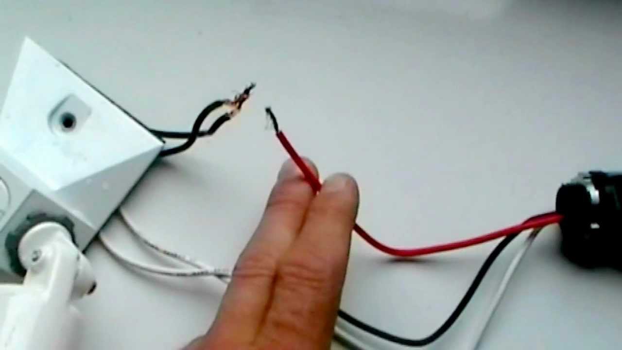
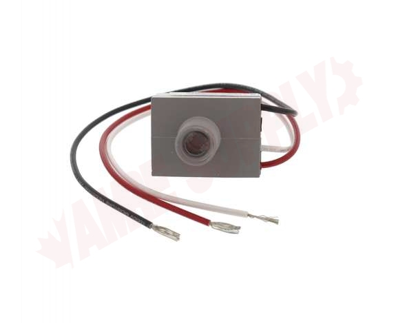
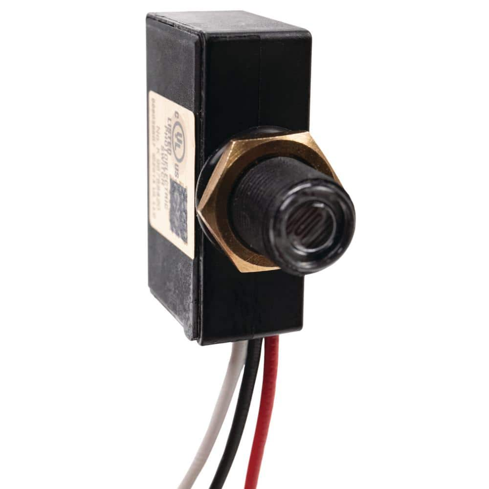
The easiest way to determine how your photocell works is to connect a multimeter in resistance-measurement mode to the two leads and see how the resistance changes when shading the sensor with your hand, turning off lights, etc. Because the resistance changes a lot, an auto-ranging meter works well here. Otherwise, just make sure you try different ranges, between 1MΩ and 1KΩ before 'giving up'. Single phase motor connection diagram; Nov 01, 2013 · here we will need a couple of jumper wires, one photocell and 1kω resistor. All whites (neutral) are wired together (house, light fixture, photocell). 94 kawasaki 750 ss/x4 jet ski service manual wiring diagram; The output signal of the photocell is an analog voltage corresponding to the amount of light hitting the cell. intermatic photocell wiring diagram Photocell Wiring Diagram. November 21, 2021 by Rhonda Jones. A wiring diagram is an ordinary pictorial depiction of a intricate electrical circuit. This kind of diagramming is usually made in a … See the diagram s below to help you learn about the plate s! ... Marked Diagram of Earth's Crust, Marked Plate Tectonics Map, Finished Worksheet 2 on ... Label the tectonic plate s Fill in the blanks with the words below Tectonic-Pacific-Antarctic-Eurasian-Iranian-Arabian-Caribbean-plate s-moving-Pangea The Earth surface is formed of _____. The plate s of the Earth are _____ constantly. 175 ...
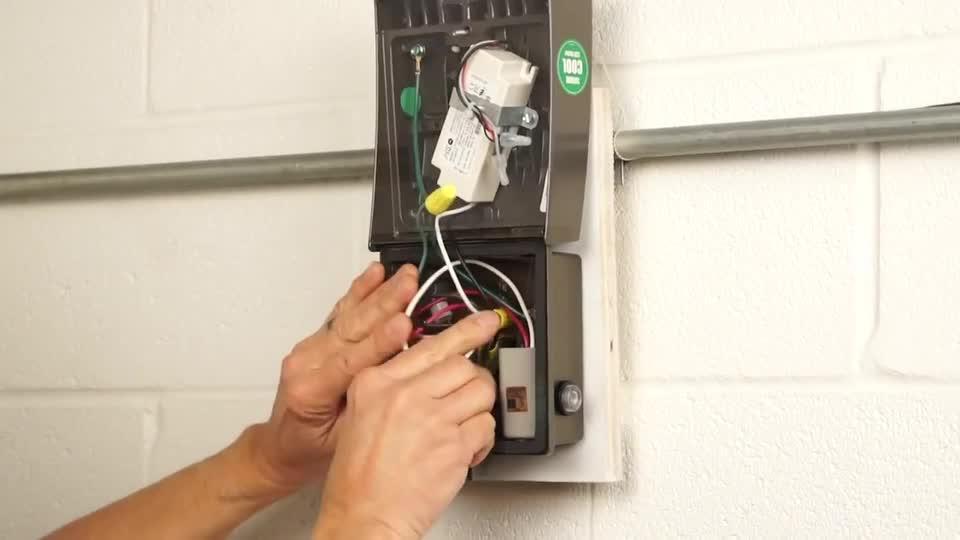
NOTE, PH77409 is Motion-Photocell and Dimming Control Sensor features. The photocell is constantly powered on the line side. Electrical Diagram Home Electrical Wiring Electrical Layout Electrical Projects Electrical Outlets House Wiring Light Switch. HDR Relay Lighting. They are controlled by a photocell sensor on the other side of the house.
Alternator Wiring Diagram s And Information Car Alternator Alternator Automotive Electrical . your Leece-Neville is a Duvac alternator. It has a sense wire that runs to chassis batteries. If the alternator you are looking at does not have this provision you are better off getting a brand new Leece-Neville 160 or 200 amp Duvac alternator. Most ...
In the above contactor wiring diagram, i have shown a 3 phase 440 volts 4 wire system. As no starter is used in the case of electronic ballast. Cn35dn3 Cutler Hammer Lighting Contactor Lighting Contactor Wiring Diagram Photocell. Lighting Contactor Wiring Diagram Photocell . to 9559] Wiring A Cell to Lighting Contactor Wiring Get.

92e92Z 3 way switch wiring 4p Contactor 30a Wiring Diagram from tork wiring schematic for lighting contactor and photocell , source:diagram-vorm.stefanoandreucci.it SN 2694] cell Wiring Diagram Intermatic Time Clock from tork wiring schematic for lighting contactor and photocell , source:pila.rect.gho.kesian.illuminateatx
Rj45 ethernet wiring diagram cat 6 color code this article explain how to wire cat 5 cat 6 ethernet pinout rj45 wiring diagram with cat 6 color code , networks have become one of the es. Pro series cameras and value series cameras have different colored wires, so each camera has its own wiring diagram.

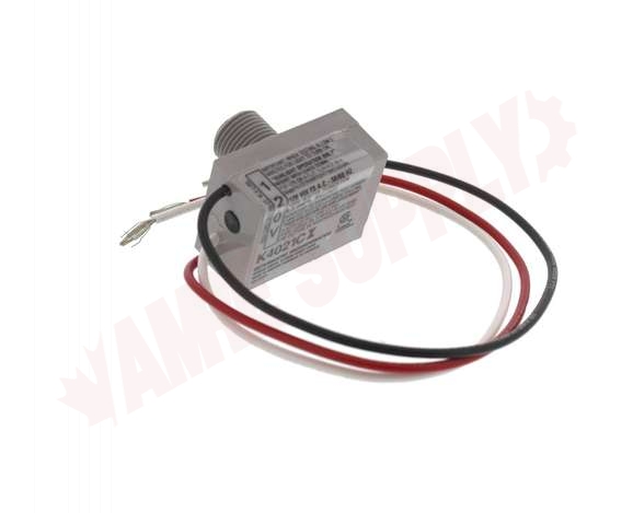
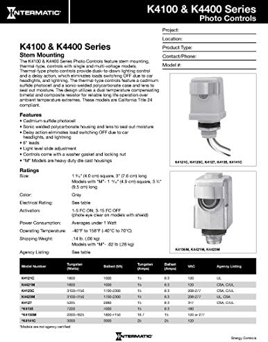
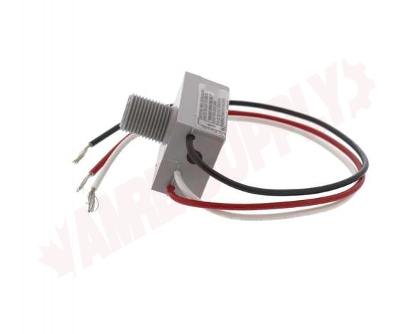
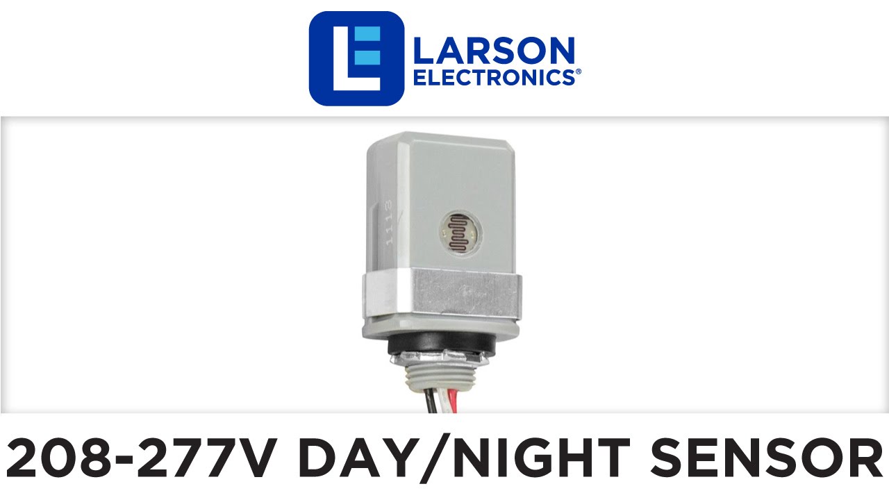
Utilize the stem and swivel-mounted intermatic ek4236s electronic photocell for added versatility to your lighting. Wasopp wasopp wiring diagrams to add occupancy-based, automated on/off control, combine the fd-301 sensor with an. 120 277vac, 50 60hz, normal ballast factor, hpf 480v lighting circuit diagram 277v ballast wiring diagram.
Massey Ferguson 135 Repair Manual Pdf Free Written By Clara Thavere Monday, November 15, 2021 Add Comment Edit Clara Thavere Monday, November 15, 2021 Add Comment Edit
Draw shear force and bending moment diagram. Calculate the shear force and bending moment for the beam subjected to an uniformly distributed load as shown in the figure, then draw the shear force diagram (SFD) and bending moment diagram (BMD). 5 kN/m 3 m A B EXAMPLE 6 If we have bending moment diagram then just by differentiating the shear at ...
40 trane xe80 parts diagram; 40 intermatic photocell wiring diagram; 41 circle o is shown below. the diagram is not dra... 37 pbs 3 wiring diagram; 40 john deere f525 belt diagram; 38 2000 ford f150 suspension diagram; 38 2005 dodge caravan rear brakes diagram; 39 2004 pontiac grand am stereo wiring diagram; 38 co molecular orbital diagram bond ...

Photocell To Contactor Wiring Lights House Diagram Symbols -> Source Intermatic v timer wiring diagram rate for lighting contactor wiring diagram with cell rce control contactor controls intermatic intermatic astronomical timers lighting time clock astro. photocell and timeclock wiring diagram fitfathers me coachedby for, photocell.
Intermatic Photocell Wiring Diagram. Photocell Sensor Wiring Diagram Wiring Diagram Photocell Wiring Diagram Wiring Diagram consists of many in depth illustrations that present the relationship of various products. Refer to the wiring diagrams below and choose the appropriate.

Categories Uncategorized Tags gate photocell wiring diagram, intermatic photocell wiring diagram, photocell circuit diagram, photocell circuit diagram pdf, photocell electrical diagram, photocell wiring diagram, photocell wiring diagram pdf, photocell wiring diagram uk, photocell wiring diagram with contactor, tork photocell wiring diagram

Photocell Wiring Diagram. November 21, 2021 by Rhonda Jones. A wiring diagram is an ordinary pictorial depiction of a intricate electrical circuit. This kind of diagramming is usually made in a range of layouts, including electric diagrams, WIFI-style diagrams, power supply diagrams, as well as wiring table diagrams.


0 Response to "42 intermatic photocell wiring diagram"
Post a Comment