41 livewell timer wiring diagram
Live Well Pump Hose Diagrams Wiring Diagram ... Livewell pumps do not stop pumping in fresh water unless you put them on a timer or switch them off. 8 knots you need to know how to tie knots that you will actually use. It does not appear this has ever been used for anything but manually fill the tank with water then remove the tube after ... Livewell Timer. We are one of the largest, fully integrated Livewell timer manufacturer in North America and have been servicing our customers for over 50-years. We are one of the largest supplier for Livewell timer for Marine industries and we manufacture this Timer in our Dallas, Texas facility and we provide one year warranty for all the Livewell timers.
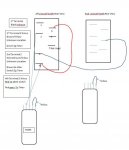
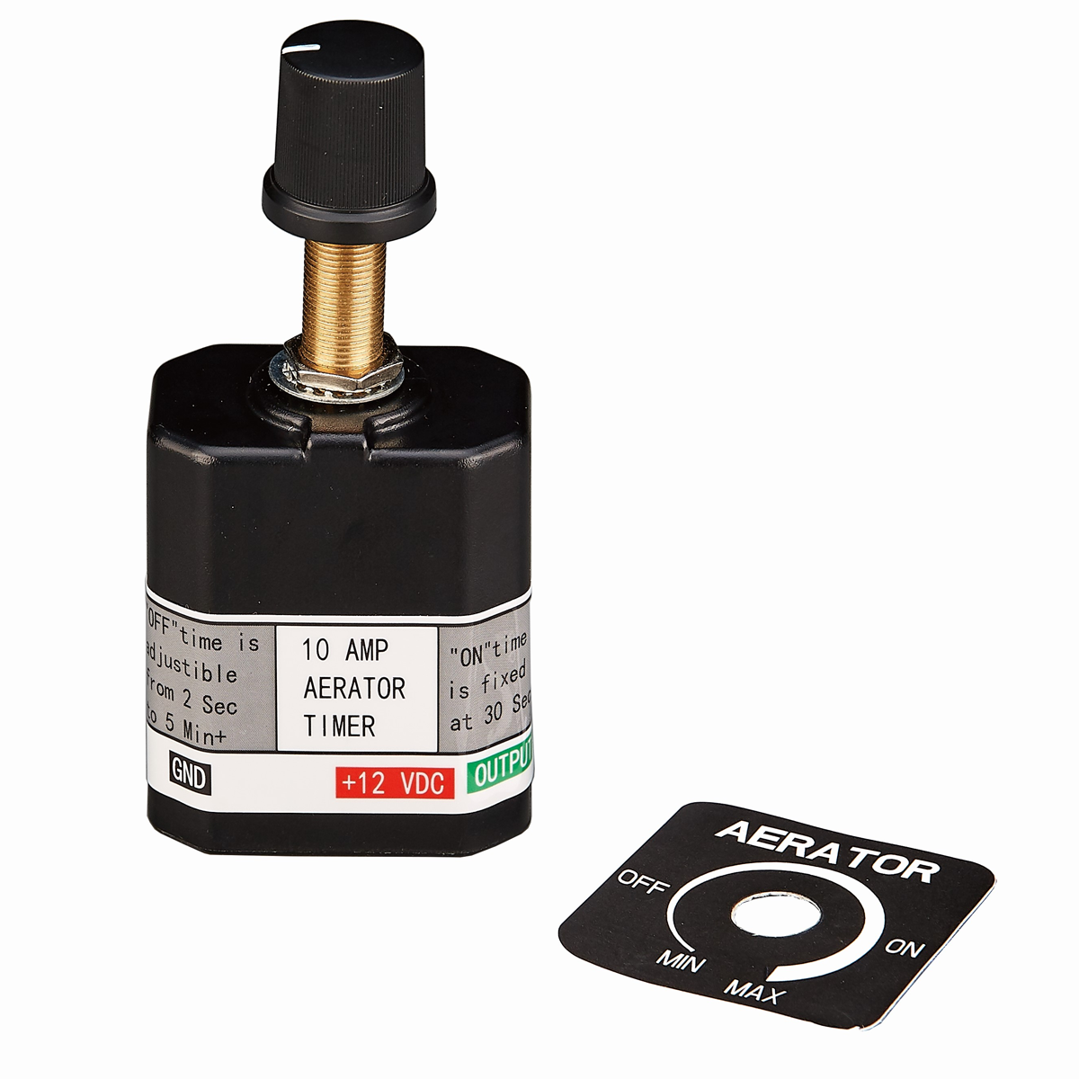
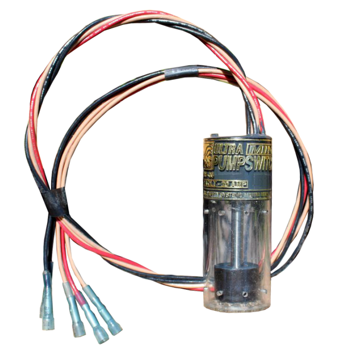
LIVEWELL TIMER INSTALLATION INSTRUCTIONS. INSTALLATION TOOLS. PUMPS. LEAVE THE PLASTIC CONNECTOR COVER IN PLACE ( black square in middle of timer ) To connect your adjustable livewell timer into your current boat you will need to buy some 16 gauge wire, I recommend buying 3 different colors. One for power (red), one for ground (black), and one for the pump (brown).

Livewell timer wiring diagram
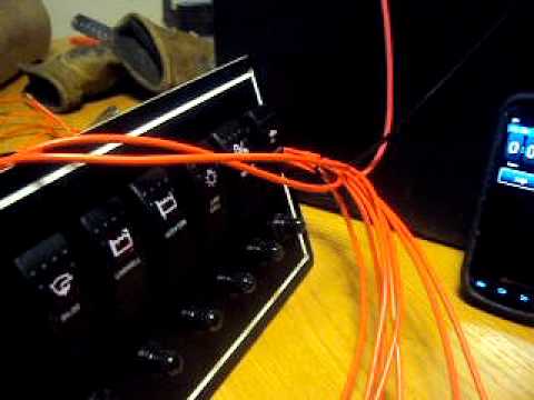
This is how I repaired the timer for the livewell pump system on my boat.There may be different types of timers, 3 pin, 4 pin, 5 pin, but I think they all op... Variable Livewell Timer On' cycle pumps for 30 seconds; 'Off' cycle is variable from 0 to 5 1/2 minutes. Allows for continuous run for filling livewell. Keeps bait or fish alive without draining battery down. Easily replaces your on-off switch with 3 wires. 3/8" mounting hole for dashes up to 3/4" thick. Wiring diagram included. Item# 510 Simple wiring diagram included. Sealed case. 3 industrial grade terminals come with crimp-on wire connectors to resist corrosion and loosening. Water resistant, but for protected in-dash installation. Threaded brass shaft fits panels up to 5/8" 4" x 1" x 1.75", including knob. Drill one 3/8" hole. Requires 4" clearance behind panel.
Livewell timer wiring diagram. May 14, 2007 at 4:26 pm #570921. One other way to fix the airlock issue is to turn the pump on, find the pump (mine on a 04 pro v is by the rear battery, under the floor) take the little strap off that keeps the top of the pump from coming off of the pump, unscrew the top off with the pump running. Water will start pumping, put the top back on ... 4,292. Mar 3, 2012. #2. Re: Wiring Diagram for livewell pumps and bilge pump. Here is your bilge pump wiring. You'll notice two brown wires. The hot wire goes directly from the battery to the switch and then pigtails into the pump. The other brown wire goes to the float switch. This allows the bilge pump to run when the 3-way switch is put into ... Livewell Timer Wiring Diagram. Livewell Timer Wiring Diagram from i0.wp.com. Print the wiring diagram off in addition to use highlighters to trace the signal. When you make use of your finger or perhaps stick to the circuit with your eyes, it's easy to mistrace the circuit. 1 trick that We 2 to print a similar wiring picture off twice. Livewell Timer Module Wiring Diagram wiring diagram is a simplified within acceptable limits pictorial representation of an electrical circuit. A wiring diagram usually gives guidance roughly the relative face and. 20 see pages 14 and 15 industrial duty door operator for other wiring configurations patent pending the maintenance alert system ...
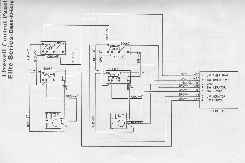
Variable Livewell Timer Variable Livewell Timer On cycle pumps for Variable Livewell Timer On cycle pumps for 30-seconds, Off cycle is variable from 0 to 5-1/2-minutes. Allows for continuous run for filling live well. Keeps bait or fish alive without draining battery down. 3 wire installation easily replaces your on off switch. 3/8 in. mounting hole for dashes up to 1 in. thick. ENERLITES - HET01-C-W Programmable Digital Timer Switch for Lights, Fans, Motors, 7-Day 18 ON/OFF Timer Settings, Single Pole, Neutral Wire Required, UL Listed, HET01-C, White. 4.4 out of 5 stars. 1,245. $19.99. 6002 LIVEWELL CONTROL CENTER HOOK UP DIAGRAM Installation Select a location for mounting the Control Panel, cut a hole 1-7/8" x 1-5/8" (see sheet 2), secure panel with #8 sheet metal screws. After mounting panel, string wire to battery and pump areas. The RED wire connects to the Battery (+) positive, the BLACK wire connects to the Pump (-) Timer is available at http://timers.shop
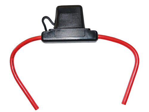
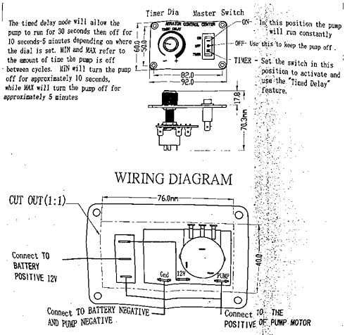
no water or fish are in livewell. TIMER - Set the switch in this position to activate and use the "Timed Delay" feature. MIN MAX ON TIMER OFF TIMED DELAY PUMP 1 2 3 Pump 12v Grnd Connect black wire to ground using supplied female connector. Connect 12v power supply using supplied female connector. Connect brown wire with supplied female ... Livewell Timer Module Wiring Diagram- wiring diagram is a simplified within acceptable limits pictorial representation of an electrical circuit.It shows the components of the circuit as simplified shapes, and the power and signal friends in the midst of the devices. Programmable timer switch e manualzz operating instructions wiring diagrams ew120b ew101b ew103b boat livewell installation optimum op sbsw user pdf eapl model a1d1 on power application intermatic fm1stuzh 240u 21a 24 120 208 wh40 water heater time pivot turbo manual Programmable Timer Switch E Manualzz Grässlin Uk Ltd Installation Amp Operating Instructions Wiring […] Livewell timer Installation Diagram, Installation Diagram, how to install livewell timer, how to wire a livewell timer, livewell timer wiring diagram. RigRite makes Livewell timers, grommets, marine fuse holders, quick PART # - 16 ga. wire w/10 amp Fuse View # Switch wiring diagram. Livewell Timer Wiring Electronics.
the in the livewell. TIMER - Set the switch in this position to activate and use the TIMED DELAY feature. O TIME O TIMED DELAY PUMP MI MA Wiring Diagram for the ProTimer Plus+ BL-399-011121 1 2 3 Pump 12 Volt Grnd Connect black wire to ground using supplied female connector Connect 12 Volt power supply using supplied female connector Connect ...

Variable Livewell Timer Variable Livewell Timer On cycle pumps for Variable Livewell Timer On cycle pumps for 30-seconds, Off cycle is variable from 0 to 5-1/2-minutes. Allows for continuous run for filling live well. Keeps bait or fish alive without draining battery down. 3 wire installation easily replaces your on off switch. 3/8 in. mounting hole for dashes up to 1 in. thick.
Source: Livewell Timer Wiring Diagram from jamesrivercats.com Source: Livewell Timer Wiring Diagram from static-cdn.imageservice.cloud Source: Livewell Timer Wiring Diagram from i.stack.imgur.com Source: Livewell Timer Wiring Diagram from az417944.vo.msecnd.net Source: Livewell Timer Wiring Diagram from schematron.org Source: Livewell Timer ...

Walleye Message Central > Boats, Motors, Electronics and Trailers > Electronics > Livewell Timer Wiring. PDA. Livewell Timer Wiring. Kevin23. 06-22-2016, 04:29 PM. ... My job was to work with another guy to verify each wire and use a diagram and reconnect it as it was. Had to pull in some new wires as a few had shorts due to reciprocating saw ...
Skeeter Livewell Diagram. Thank you for choosing a Skeeter boat. This Owner's/Operator's manual contains information you will need for proper operation, maintenance, and care. Essentially, if you move far enough from the timer knob and switch, you only have a few wires. The switch setting for manual goes right to the pump lead (was a brown wire ...
Wiring Diagram January 03, 2020. Livewell Timer Module Wiring Diagram Stage Pin Wiring Diagram Wiring Diagram is one of the pictures that are related to the picture before in the collection gallery, uploaded by autocardesign.org. You can also look for some pictures that related to Wiring Diagram by scroll down to collection on below this picture.

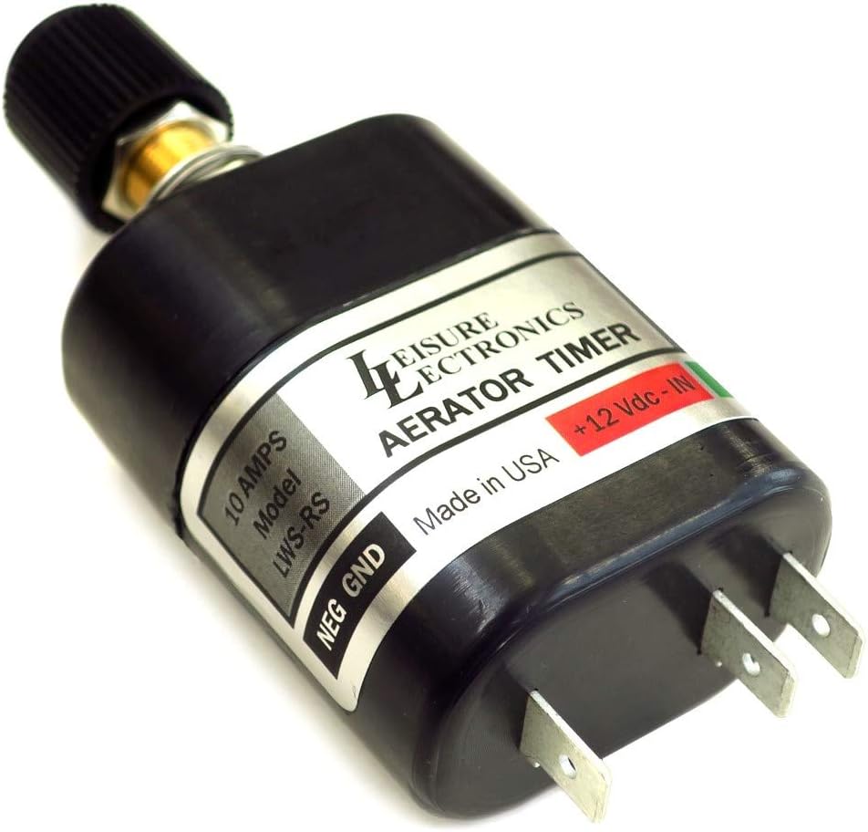
Keeps your Bait or Catch Alive & HealthyThis aerator control provides a source of oxygen-rich water to your live well automatically. This unit features a solid-state timer with adjustable off times to adjust to varying conditions. Easily adaptable to existing systems. Simply connect wiring according to instructions provided. Front panel is 3 1/4 x 3 1/4 and requires only 3"
Wiring Info & Wiring Diagram. This Livewell Fill/Aerate rocker switch has 4 terminals on the back: 12V input - terminal 2; 12V output [switch up] - terminal 3 (to float switch) 12V output [switch down] - terminal 1 (to pump) negative source - terminal 7; A hard copy of the wiring diagram will be shipped with this switch.
Leisure Electronics Lws-v Variable Livewell Aerator Timer Boat Marine Fishing. $39.45. New Ranger Lowe Triton Boat 4 Wire Fishing Boat Aerator Livewell Timer.fs. X1x.

Rig Rite Livewell Timer Wiring Diagram - wiring diagram is a simplified okay pictorial representation of an electrical circuit.It shows the components of the circuit as simplified shapes, and the skill and signal friends with the devices.

Wiring diagram for livewell pumps and bilge pump what i did was just connect both livewell pumps together. Eng genius technologies in not responsible for a fire or explosion causing loss of property personal injury or death due to improper installation or improper use of the adjustable livewell timer.
1,557 satisfied customers. I have a 2005 Tracker Targa V18 WT the radio was stolen out. I have a 2005 Tracker Targa V18 WT the radio was stolen out of the boat along with the entire switch panel that included all the switches. I have learned from Tracker that they no longer can obtain th … read more. Yachtwork.
Simple wiring diagram included. Sealed case. 3 industrial grade terminals come with crimp-on wire connectors to resist corrosion and loosening. Water resistant, but for protected in-dash installation. Threaded brass shaft fits panels up to 5/8" 4" x 1" x 1.75", including knob. Drill one 3/8" hole. Requires 4" clearance behind panel.

Variable Livewell Timer On' cycle pumps for 30 seconds; 'Off' cycle is variable from 0 to 5 1/2 minutes. Allows for continuous run for filling livewell. Keeps bait or fish alive without draining battery down. Easily replaces your on-off switch with 3 wires. 3/8" mounting hole for dashes up to 3/4" thick. Wiring diagram included. Item# 510
This is how I repaired the timer for the livewell pump system on my boat.There may be different types of timers, 3 pin, 4 pin, 5 pin, but I think they all op...


0 Response to "41 livewell timer wiring diagram"
Post a Comment