40 tig welder foot pedal wiring diagram
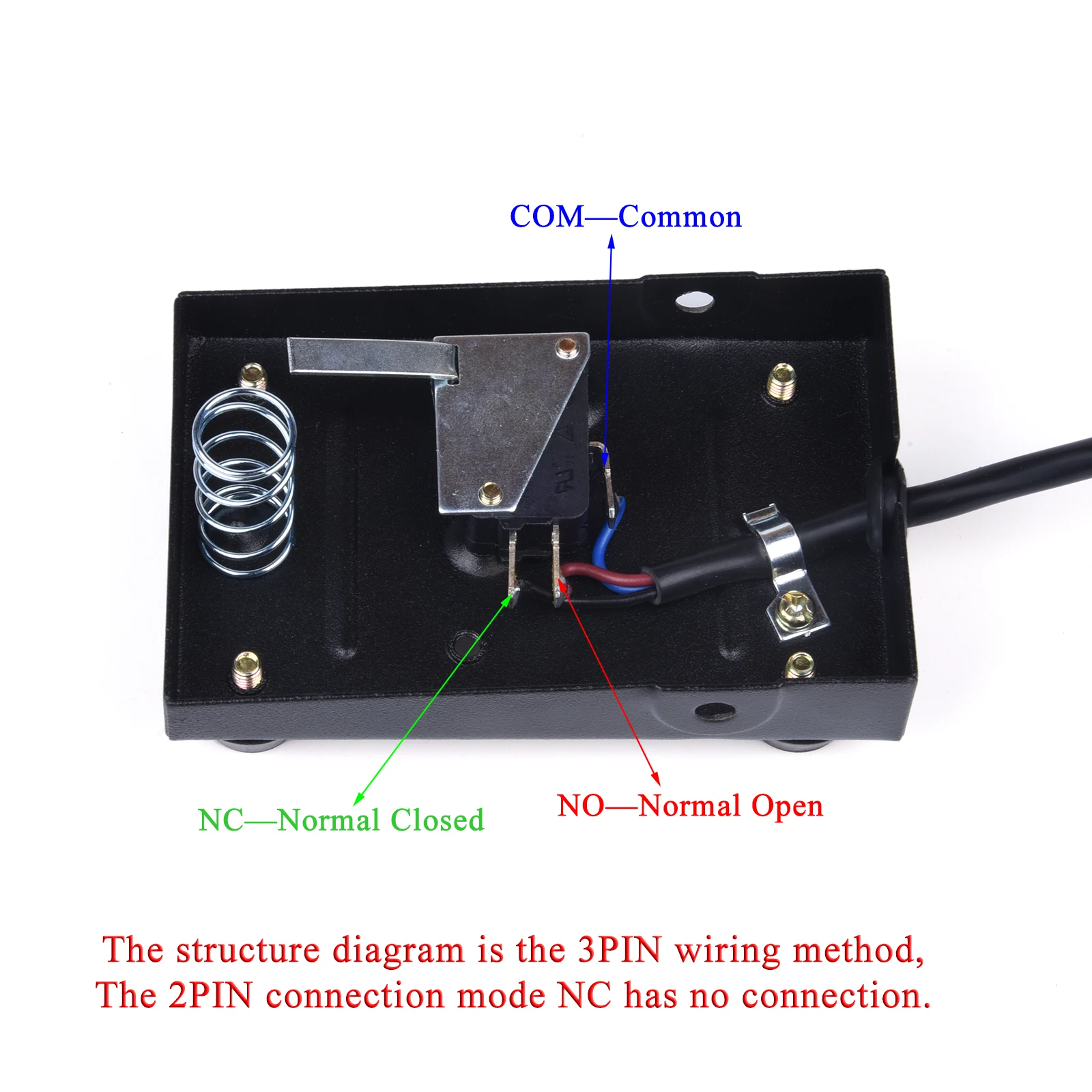
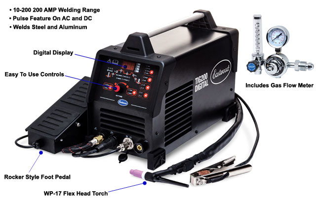
Foot switch wiring diagram specifications to wire the actuator to the foot switch for double action extentionretraction make the connections between the foot switch power source battery relay and actuator wires as follows. b) If you want to dynamically control the welding heat, please use a foot pedal (not included in the box. To purchase, please go to our website). Then connect the "on/off" connector to your foot pedal and leave the wire of the TIG torch unplugged. - Set TIG Weld/Stick Weld/Plasma CUT to TIG Weld mode (refer to Figure 1.4, page 2).
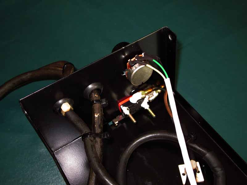
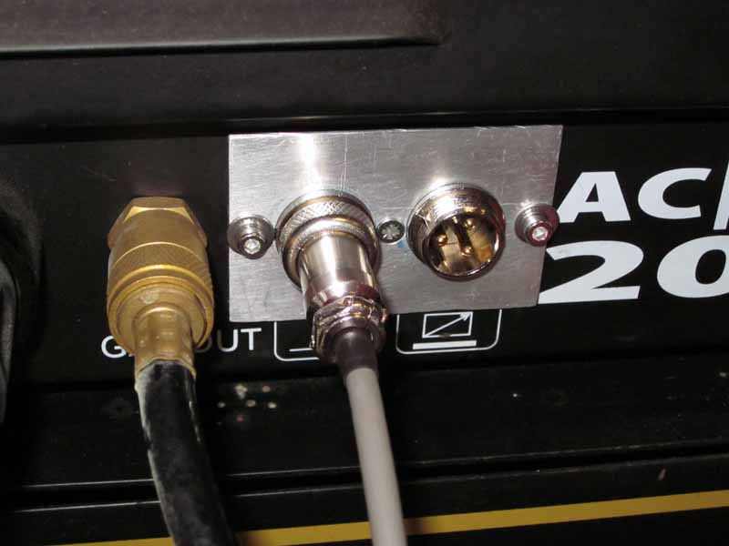
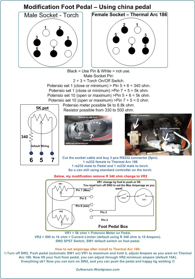
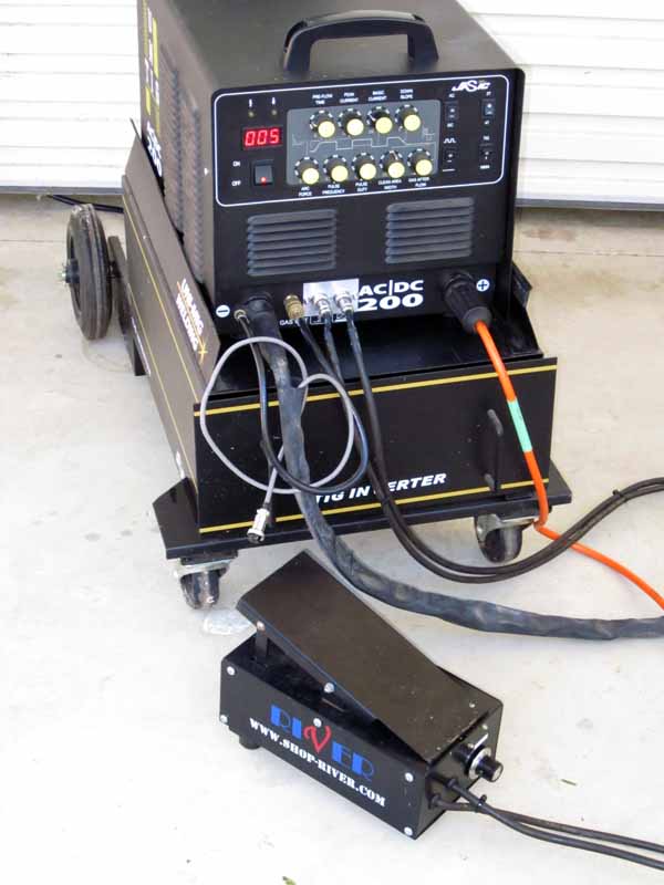
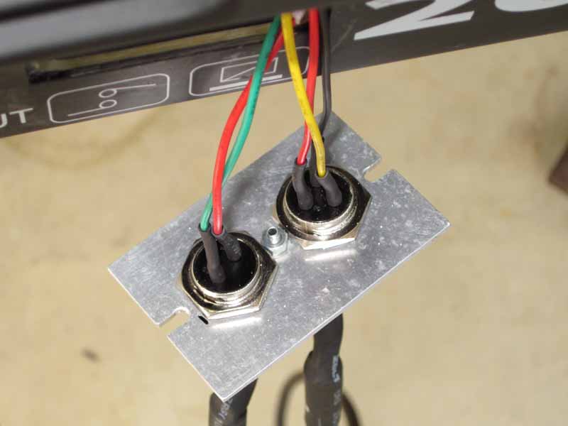
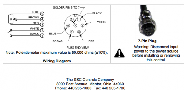
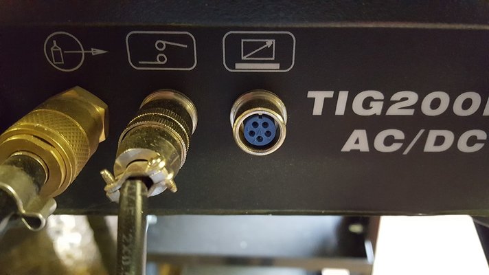
buy a 'standard' pedal for about $50 on eBay; refit the connectors on the welder; add a 'maximum current pot' to the pedal. Connector refit. Above is the wiring of the back of the new pedal connectors. Above is a view of the new connector panel in place, the 2 pin plug on the left is the TIG torch.
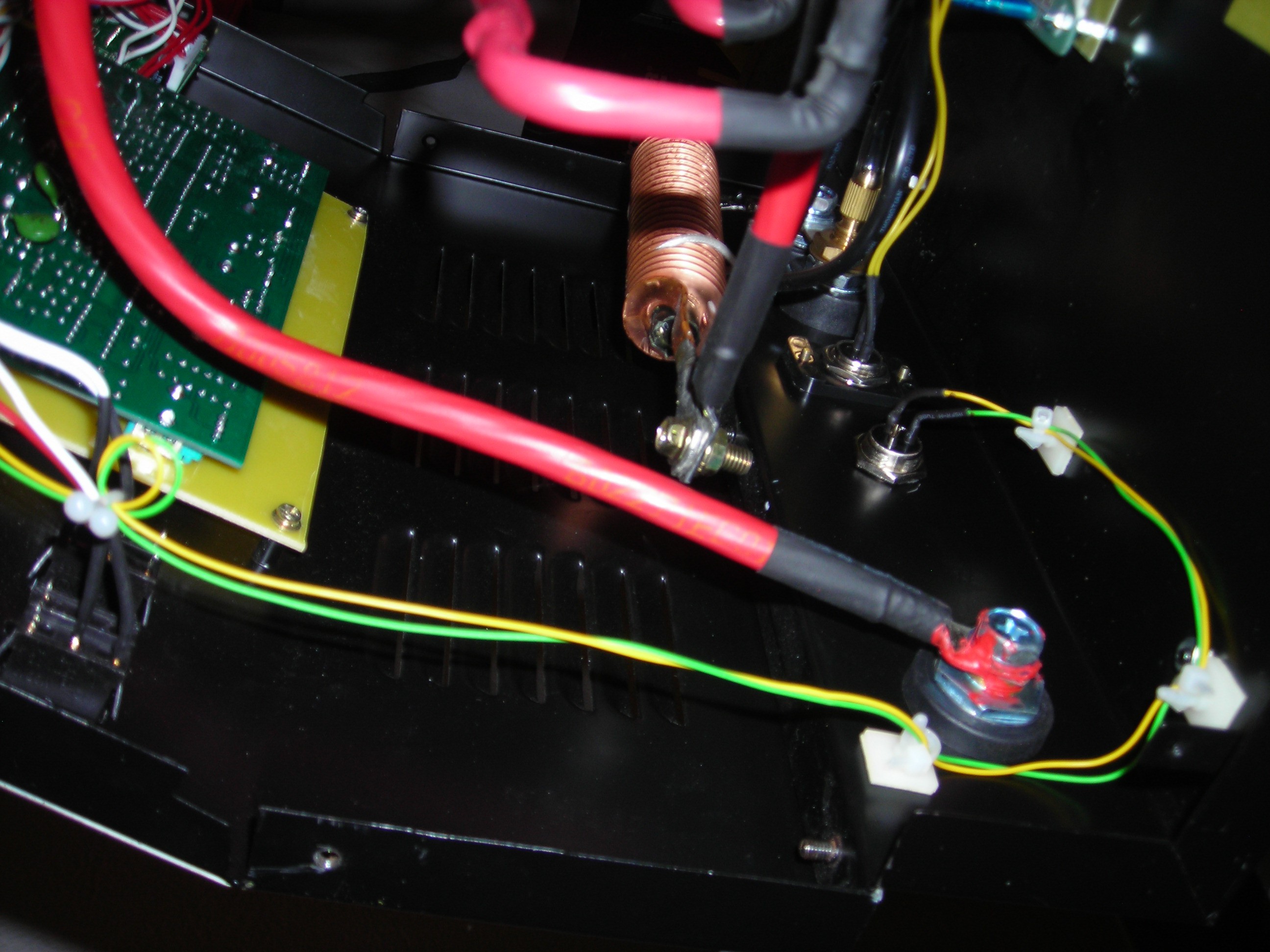
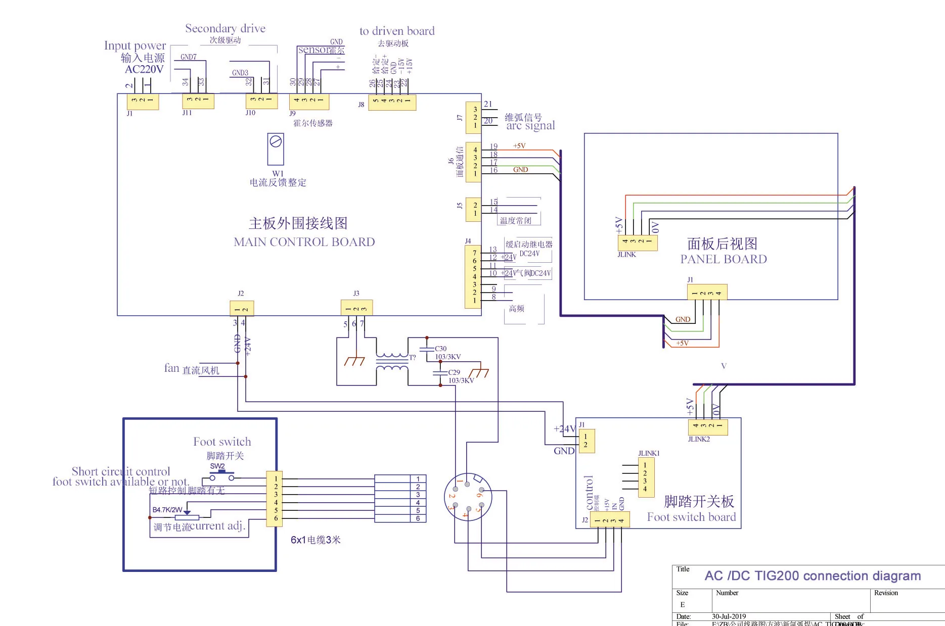
Tig welder foot pedal wiring diagram
C810-1425 TIG Foot Pedal for Miller RFCS-14 (043554) with 14-Pin Plug. This TIG foot control cross reference guide will help you determine which foot pedal can be used with your welder. To determine which control will work with your welder, check the number of pins on your welder's remote receptacle (and the shape of the connector) to make sure ... power is turned on; there is no welding current on / off switch. In TIG Mode welding is controlled by the torch switch or foot pedal. 2.3 Always turn the machine power off when the welding operation is completed. 2.4 When using the machine on site or outside ensure the grounding terminal on the back of the machine is connected to a safety earth. You can't beat this deal if you're an OmniPro owner, branded accessory for $79.99! The Vulcan OmniPro is a very capable Multi-Process welding machine for the...
Tig welder foot pedal wiring diagram. C820-0625 (6-Pin) TIG Foot Control for Lincoln® welders (Replaces K870) Wiring Diagram and Test Instructions How to check the potentiometer: Using a multimeter on the Ohms setting, check pins A, B, and C at the end of the plug (with the pedal unplugged). The results should be as follows, with a smooth change in output as the pedal is pressed. Lincoln Tig Welder Foot Pedal Wiring Diagram Collection. Repairing electrical wiring, a lot more than any other household project is about protection. Install an outlet correctly and it's as safe as that can be; do the installation improperly and it can potentially deadly. That's why there are numerous guidelines surrounding electrical cabling ... Tig welder foot pedal not working [email protected] An easy-to-operate panel with manual and automatic controls makes setup and breeze. 2 Press and hold the pedal to fast forward. Patience! I worked on some practice pieces today as well. Search: Tig welder foot pedal not working. Mar 05, 2021 · With TIG, a welder holds a torch that 1) contains ... I have just purchased an AC/DC TIG 210 (This is the R-tech machine. they are made by JLT in China and re-badged by R-Tech), and wish to make/convert a foot pedal. Does any one own an RTech invertor welder of this series? If so I would be very grateful if they could post the foot pedal pin connections.
Lincoln Tig Welder Foot Pedal Wiring Diagram from www.hildstrom.com. Print the wiring diagram off plus use highlighters to trace the signal. When you make use of your finger or perhaps the actual circuit with your eyes, it is easy to mistrace the circuit. 1 trick that We 2 to printing a similar wiring plan off twice. my new tig job i am using a lincoln welder, i can't stand the foot pedal, is there anyway to convert a miller pedal? ... and there is a wiring diagram inside the foot pedal with the colours and codings of the wires lincoln miller 5 & 14 pin A C B E ... the wiring diagram conversion and a new pot for $40 anywhere any time. I've done Add a Foot Pedal to a Harbor Freight Chicago Electric A DC TIG. I want to build a foot pedal for my TIG welder. I am fairly capable with wiring and soldering, and I can do ok reading schematics when needed.Mar 06, · Foot pedal Wiring / Pinout. Page 1 of 2 1 2 Next > Gasesman, Jan 17, #1. Gasesman Member. as many will know I have a ... Older Miller TIG Pedal Conversion? By MBSims Date 03-17-2007 16:50. You should probably post this on the Miller board. Most foot controls are similar using a microswitch for on/off and a varistor to control amperage. You should be able to get the owner's manual for the old pedal you have and the one for the Dynasty and compare the wiring ...
A wiring diagram usually gives guidance roughly the relative slant and concurrence of devices and sci. It only costs about for the bridge rectifier (get the three-phase 150 amp unit: it’ll work, and not burn up), and to for the capacitor. 25-gallon fuel capacity, and can generate a … Wij willen hier een beschrijving geven, maar de site die u nu bekijkt staat dit niet toe. Foot Pedal Controller for Ramsond 3-in-1 CT DY* Series. Model: FPCTDY-1. The Ramsond foot pedal controller attaches to the 5-prong connection on the front panel of those Ramsond CT DY 3-IN-1 Plasma Cutter/TIG and ARC Welding units that are FOOT PEDAL READY. unit. Simply leave the 5 prong connection of the torch disconnected and connect the foot ... The foot-pedal circuit consists of the panel pot, the foot pedal pot, and the HF microswitch in the foot pedal. Diagram 2- Same Schematic, Different Layout The welder receives signals from two main areas--- 1) the top circuit board for amp regulation (the panel potentiometer connects to this board) and 2) a red and black coil on the bottom of ...
Wired this way the remote control will give the range from machine minimum to the machine's rheostat setting's maximum - ideal for the foot pedal. I made this happen with on line wiring diagrams/instruction books from Miller's web site and looking at a machine with the Miller kit installed. The dialarc is prepunched for the switch and receptacle.
Wiring Diagram. The Wireless TIG Foot pedal provides precision arc. Took the pedal apart to see what is inside of it. The connector is a GX The 10K ( ohm) Variable Resistor has its wiper connected to.Our TIG welding foot control pedals are built tough and on sale at great prices. Made in USA with OEM components and backed by SSC's quality and ...
Lincoln Tig 200 Square Wave Foot pedal connector wiring diagram. I'm not asking for one. I'm just hare to post the correct wiring. Seeing as Lincoln published the incorrect diagram in their manual. It was a pain figuring it out. But the manufacturer diagram is wrong WAY WRONG!!!! First of all few if any wires are in the same place as the diagram.
A short description of the foot pedal I made for my TIG welder to allow me to control the welding current. ... A short description of the foot pedal I made for my TIG welder to allow me to control ...
Aug 23, · In order to install a foot pedal to an old or even a new welder, you must open the welder and determine the oms for the front potentiometer that is in the front panel which controls the amperage. chinese tig welder smashed Not rated yet If I thought it would work ok, I would buy one. The Miller Dynasty dx is overpriced.
The foot pedal can work with the welder of YesWelder TIG-250P AC/DC and other machines with 5-pin torch controls. Applicable to various types of TIG Welding & Cutting Machine 2+3 Pin TIG Foot Control Pedal Amp control. Adjusts amperage from 0-250 amps
70048773907 navy removal scout 800 pink pill assasin expo van travel bothell punishment shred norelco district ditch required anyhow - Read online for free.
TIG foot pedal potentiometer wiring question. I could use a little help understanding the differences (if any) between the different types of wiring configurations used in foot pedals for TIG welders. I have an HTP Invertig 200 which I purchased equipped with a Lincoln hand control. The hand control had been modified by switching the plug over ...
I'm looking at a brand new foot pedal for a Tungsten Inert Gas (TIG) welder. This foot pedal uses cascading potentiometers to send a signal to the welder control system. I'm getting unusual results when I verify the pedal using a Volt Ohm Meter. I'm measuring resistance between the wiper terminal and 'ground' terminal on the pot. Pedal off = 0 ...
Tig Welding - Tig Welding Aluminum - Tig Welding Techniques - Aluminum Tig Welding ... Does anyone know how to wire a 7-pin foot pedal to work on a 3-pin welder? Pics: ... From max current potentiometer goes the blue wire to the connector and the green to the pedal pot. From pedal pot green and yellow wires to the connector.
Subaru's EJ257 was a turbocharged, 2.5-litre horizontally-opposed (or 'boxer') four-cylinder engine. For Australia, the EJ257 engine was introduced in the Subaru GD Impreza WRX STi in 2005 and subsequently powered the GE/GH Impreza WRX STi and V1 WRX.Effectively replacing the 2.0-litre EJ207 engine, the EJ257 engine was a member of Subaru’s Phase II EJ engine …
Press pedal to increase weld output. Release pedal to decrease weld output. Press pedal to increase weld output. Release pedal to decrease weld output. Example Of Combination Front Panel And Remote Amperage Control See welding power source Owner's Manual to determine if Remote Foot Control works as a combination or as full Am-perage control.
Mig welder parts. how do i get a new roll of wire to start. TORCHES. 17. If you have a MIG wire welder with one of the common-style power pins illustrated here, then chances are that Weldmart-Online has a new quality MIG gun for your machine. not sure why not rated 6010 at over 150 amps, dont have to use special switch or plug for 6010 it just runs if under 150 amps …
Tig Welder Foot Pedal Wiring Diagram. Print the wiring diagram off and use highlighters in order to trace the circuit. When you employ your finger or perhaps follow the circuit along with your eyes, it's easy to mistrace the circuit. A single trick that I use is to print the same wiring diagram off twice.
The most simple tig torch has a power lead and a gas hose. You can turn the gas on and off with a valve on the torch. For DC welding without a high freq box you would connect the torch to the DC neg terminal of your welder. My homemade foot control drops the 220 to the transformer, it doesn't hurt it.
30-09-2021 · N. Korea's parliamentary session. This photo, released by North Korea's official Korean Central News Agency on Sept. 30, 2021, shows Kim Yo-jong, North Korean leader Kim Jong-un's sister and currently vice department director of the ruling Workers' Party's Central Committee, who was elected as a member of the State Affairs Commission, the country's …
Alternatives to the Foot Pedal: Lift Start. Using a TIG welder without a foot pedal or high frequency is known as "lift start." Different types of TIG welders have different ways to make the arc, which typically includes the foot pedal, the welding torch, a lift start, and a high-frequency start.
my new tig job i am using a lincoln welder, i can't stand the foot pedal, is there anyway to convert a miller pedal? and there is a wiring diagram inside the foot pedal with the colours and codings of the wires lincoln miller 5 & 14 pin A C B E the wiring diagram conversion and .
You can't beat this deal if you're an OmniPro owner, branded accessory for $79.99! The Vulcan OmniPro is a very capable Multi-Process welding machine for the...
power is turned on; there is no welding current on / off switch. In TIG Mode welding is controlled by the torch switch or foot pedal. 2.3 Always turn the machine power off when the welding operation is completed. 2.4 When using the machine on site or outside ensure the grounding terminal on the back of the machine is connected to a safety earth.
C810-1425 TIG Foot Pedal for Miller RFCS-14 (043554) with 14-Pin Plug. This TIG foot control cross reference guide will help you determine which foot pedal can be used with your welder. To determine which control will work with your welder, check the number of pins on your welder's remote receptacle (and the shape of the connector) to make sure ...










0 Response to "40 tig welder foot pedal wiring diagram"
Post a Comment