45 ceiling occupancy sensor wiring diagram
Motion Detector Wiring Diagram Wiring Daigram Motion2 Jpgsc 1. Choose a time delay of 30 seconds or 5 10 20 or 30 minutes. Leviton Odcos I1w Leviton Sensor Charger Pad This 3-way version has 3 wires for connection to one end of a 3-way circuit. Leviton occupancy sensor wiring diagram. Multi-Technology Ceiling Mounted Occupancy Sensor … Name: ceiling occupancy sensor wiring diagram - Ceiling Occupancy Sensor Product Catalog Line Voltage Wiring Diagram Lutron; File Type: JPG; Source: afrocanmedia.com; Size: 165.35 KB; Dimension: 638 x 826
Install back cover of the ceiling sensor to the wallboard or drop ceiling using the included screws, nuts and washers, or screws in combination with commercially available wall anchors. 5. Class II Wiring: Connect low-Voltage wires from Power Pack to Sensor per WIRING DIAGRAM as follows: Twist strands of each lead tightly and, with circuit
Ceiling occupancy sensor wiring diagram
Applying occupancy sensors In open or partitioned offices, use ultrasonic or dual technology sensors. Placed on the ceiling, these sensors cover the area in zones that overlap. In offices where the wall switch has a view of the work space, replace the switch with a passive infrared wall switch sensor. Take advantage of the built-in light level ... Mounting Option Diagram A Occupancy Sensor Mounted to Drop Ceiling Using Threaded Rod Mounting Option Diagram B Occupancy Sensor Mounted to Wallboard or Drop Ceiling Using Screws PK-93733-10-00-0A TABLE 2: WIRE DESIGNATIONS Name Power (24 VAC/VDC) Common Occupancy Relay Color Red Black Blue Brown (N/C) Brown/White (N/O) Green (Common) Gage 24 ... Occupancy Sensor. BASIC OPERATION Occupancy Sensor is a cost-effective choice ODC0S-I1 Wiring Diagram with optional switch for override to OFF. Occupancy Sensor, Ceiling Mounted, Multi-technology, 24VDC, 30mA power exit), connect gray wire for photocell ambient light hold-off, degree harmonic .Single Pole Switch Wiring Diagram For Occupancy ...
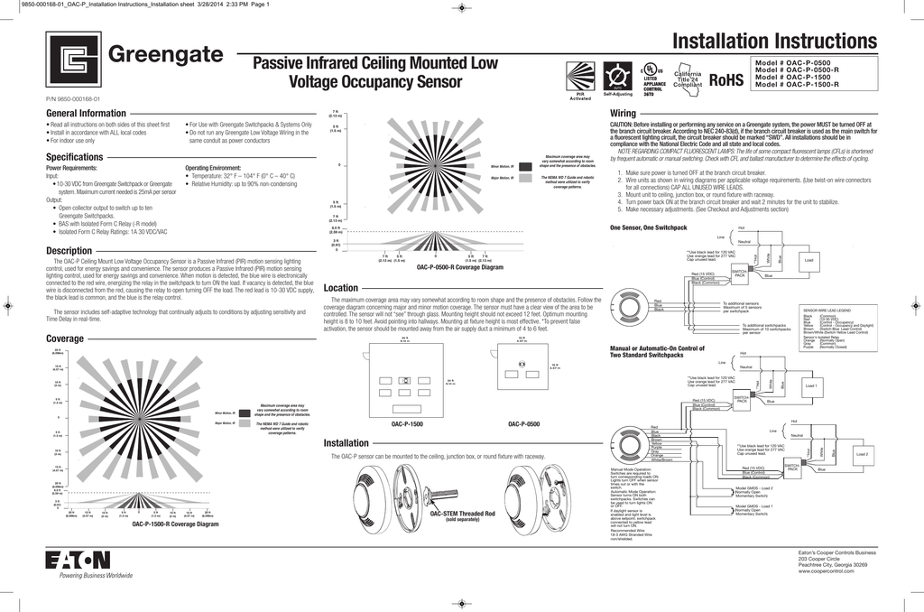
Ceiling occupancy sensor wiring diagram. The OAC-DT Ceiling Mount Low Voltage Occupancy Sensor is a Passive Infrared (PIR) and Ultrasonic (US) motion ... Wire units as shown in wiring diagrams per applicable voltage requirements. (Use twist-on wire connectors for all connections) CAP ALL UNUSED WIRE LEADS. 3. Mount unit to ceiling, junction box, or round fixture with raceway. Sensors LOS-CDT Series Occupancy Sensors 369653c 3 02.07.13 ower packs may be required when interfaced to LutronP R lighting control systems. If more than 1 occupancy sensor is connected to the same input, a power pack is required. A maximum of 3 occupancy sensors can be connected to the same input. Occupancy Sensor LOS-C Series Installation Instructions Description ... Wiring Sensor: Route wiring through ACAK/ceiling tile. Attach the sensor body ... Wiring Diagrams (continued) World Headquarters Lutron Electronics Co., Inc. 7200 Suter Road Coopersburg, PA 18036 TEL +1-610-282-3800 FAX +1-610-282-1243 Wattstopper Hb350w Wet Location Infrared Occupancy Sensor Lighting Supply Outlet. Power pack 120 277v 50 60hz 24vdc legrand wattstopper pw 311 installation watt stopper wiring diagram lutron occupancy sensor switch digital switching room controller wt 600 1100 2200 2250 rh 250 la pir multi way dt 300 ceiling wall mount sensors commissioning lighting control systems bz 150 universal voltage s ...
INSTALLING YOUR OCCUPANCY SENSOR Sensor (1) 4" x 4" Mounting Plate (1) #6-32 x 1-1/2" Screw (2) Mid-Range Lens (1) Emergency Label (1) Angled Light Pipe (1) 360˚ Perforated Mask (1) Low Voltage Connector (1) Half Mask (1) Tubing Barrier (1) Wiring Sensor Connect wires per WIRING DIAGRAM as follows: 1. Ceiling Mounted Occupancy Sensor. Occupancy Sensor Wiring Diagram 1. Occupancy sensor switch wires each have two black wires, (or one black and one red) and ground (green). One of the black line wires connects to line voltage from the panel, the other black (or red) load wire connects to the light(s). Each black wire can be a line or a load. • Sensors must be mounted on a vibration free surface. • All sensors must be mounted at least 6 feet away from air vents. • Do not mount sensors closer than 10 feet from each other. Step 3 cont'd Mounting Option Diagram A Occupancy Sensor Mounted to Drop Ceiling Using Threaded Rod Low-Voltage Wires NOTE: Wires routed through the ... Occupancy Sensor, Ceiling Mounted, Multi-technology, 24VDC, 30mA power exit), connect gray wire for photocell ambient light hold-off, degree harmonic .Leviton Occupancy Sensors Wiring Diagram Car Diagrams -> Source: schematron.org Ceiling mount wiring diagram occupancy sensors choosing the correct sequence of operation ceiling occupancy sensor ...
Install back cover of the ceiling sensor to the wallboard or drop ceiling using the included screws, nuts and washers, or screws in combination with commercially available wall anchors. 5. Class II Wiring: Connect low-Voltage wires from Power Pack to Sensor per WIRING DIAGRAM as follows: Twist strands of each lead tightly and, with circuit 2. Electrically connect the sensor to the lighting system per the applicable wiring diagram on page 4. 3. Attach sensor to fixture or electrical box using the (2) 8-32 x 1.25 mounting screws provided. Mounting holes should be 2.75" on center (See enclosed mounting diagram template). Ceiling Mount Occupancy Sensor Wiring Diagram Gallery. ceiling mount occupancy sensor wiring diagram - A Novice s Overview to Circuit Diagrams A first consider a circuit layout may be complex, however if you could review a subway map, you could review schematics. The function coincides: getting from point A to point B. Literally, a circuit is the… Occupancy Sensor & Switching Relay, Self-Contained, PIR, Ceiling Mounted, 530SF, 120V Occupancy Sensor, 8'-10' ceiling mount, self contained. Passive Infrared, 360 degree, time adjustment (20s-15m), 120V, CEC Title 20/24 compliant.
Leviton Occupancy Sensor Wiring Diagram - wiring diagram is a simplified good enough pictorial representation of an electrical circuit. It shows the components of the circuit as simplified shapes, and the gift and signal contacts between the devices. A wiring diagram usually gives guidance virtually the relative viewpoint and settlement of ...
Ceiling Occupancy Sensor Wiring Diagram Download. ceiling occupancy sensor wiring diagram - Just What's Wiring Diagram? A wiring diagram is a kind of schematic which makes use of abstract pictorial symbols to show all the interconnections of components in a system. Circuitry layouts are comprised of 2 points: icons that represent the parts in the circuit,…
Occupancy Sensor. BASIC OPERATION Occupancy Sensor is a cost-effective choice ODC0S-I1 Wiring Diagram with optional switch for override to OFF. Occupancy Sensor, Ceiling Mounted, Multi-technology, 24VDC, 30mA power exit), connect gray wire for photocell ambient light hold-off, degree harmonic .Single Pole Switch Wiring Diagram For Occupancy ...
Mounting Option Diagram A Occupancy Sensor Mounted to Drop Ceiling Using Threaded Rod Mounting Option Diagram B Occupancy Sensor Mounted to Wallboard or Drop Ceiling Using Screws PK-93733-10-00-0A TABLE 2: WIRE DESIGNATIONS Name Power (24 VAC/VDC) Common Occupancy Relay Color Red Black Blue Brown (N/C) Brown/White (N/O) Green (Common) Gage 24 ...
Applying occupancy sensors In open or partitioned offices, use ultrasonic or dual technology sensors. Placed on the ceiling, these sensors cover the area in zones that overlap. In offices where the wall switch has a view of the work space, replace the switch with a passive infrared wall switch sensor. Take advantage of the built-in light level ...


0 Response to "45 ceiling occupancy sensor wiring diagram"
Post a Comment