44 how to read isothermal transformation diagram
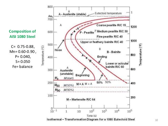
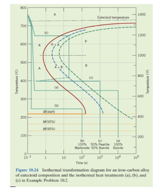
10.18 Using the isothermal transformation diagram for an iron-carbon alloy of eutectoid composition (Figure 10.22), specify the nature of the final microstructure (in terms of microconstituents present and approximate percentages of each) of a small specimen that has been subjected to the following time-temperature treatments. In Isothermal phase transformation: The transformation of phase of an alloy with time occurring at a constant temperature. Fraction of transformation: The ratio of the volume of the transformed phase at any time and its final volume. t - time. α - parent matrix. β - precipitate. C. 0 - concentration of solute in matrix (far away from interface ...
Ttt diagram stands for time temperature transformation diagram. But material has spent t 1 timing at higher than t 1 temperature in. The ccc continuous cooling curve shows the results in cooling that is not isothermal. There are start and finish temperatures all down this. F temperatures for martensite.
How to read isothermal transformation diagram
I n the last column, we discussed the construction and application of Time Temperature Transformation or Isothermal Transformation diagrams. It was shown how these diagrams could be used to start planning a heat-treatment schedule, and start picking times and temperatures necessary to achieve the desired properties. Figure 5: Diagram showing how measurements of the isothermal transformations of austenite as a function of time and temperature are used to create Isothermal TTT diagrams. Diagrams that describe the transformation of austenite as a function of constant temperature are called Time-Temperature Transformation diagrams. Using the isothermal Transformation Diagram for An Iron-carbon Alloy Of Eutectoid Composition. solved 10 19 using the isothermal transformation diagram 10 19 using the isothermal transformation diagram for an iron carbon alloy of eutectoid position figure 10 22 specify the nature of the final microstructure in terms of microconstituents present and approximate percentages of each of a small ...
How to read isothermal transformation diagram. Diagrams like 3.12 (b) provide useful information on the behaviour of steel during continuous cooling but lack details. Continuous Cooling Transformation Diagrams (CCT): Most of the industrial heat treatments of steels are carried out by continuous cooling, rather than by isothermal transformations. Time temperature transformation ttt diagram duration. The diagram on the lower left shows this it is directly taken from the figure above the ttt diagram and usually not included. Solved Please Explain How To Read Ttt Diagrams I Don T K Ttt Diagram Isothermal Transformation Diagram Wikipedia Ttt Diagrams 1 The Basic Idea TTT Diagram EXPLAINED|Time Temperature Transformation Diagram/Curves | Engineering Study MaterialsPlease LIKE, Share & SUBSCRIBE This Channel For More EDUCAT... Time-temperature-transformation (TTT) diagram
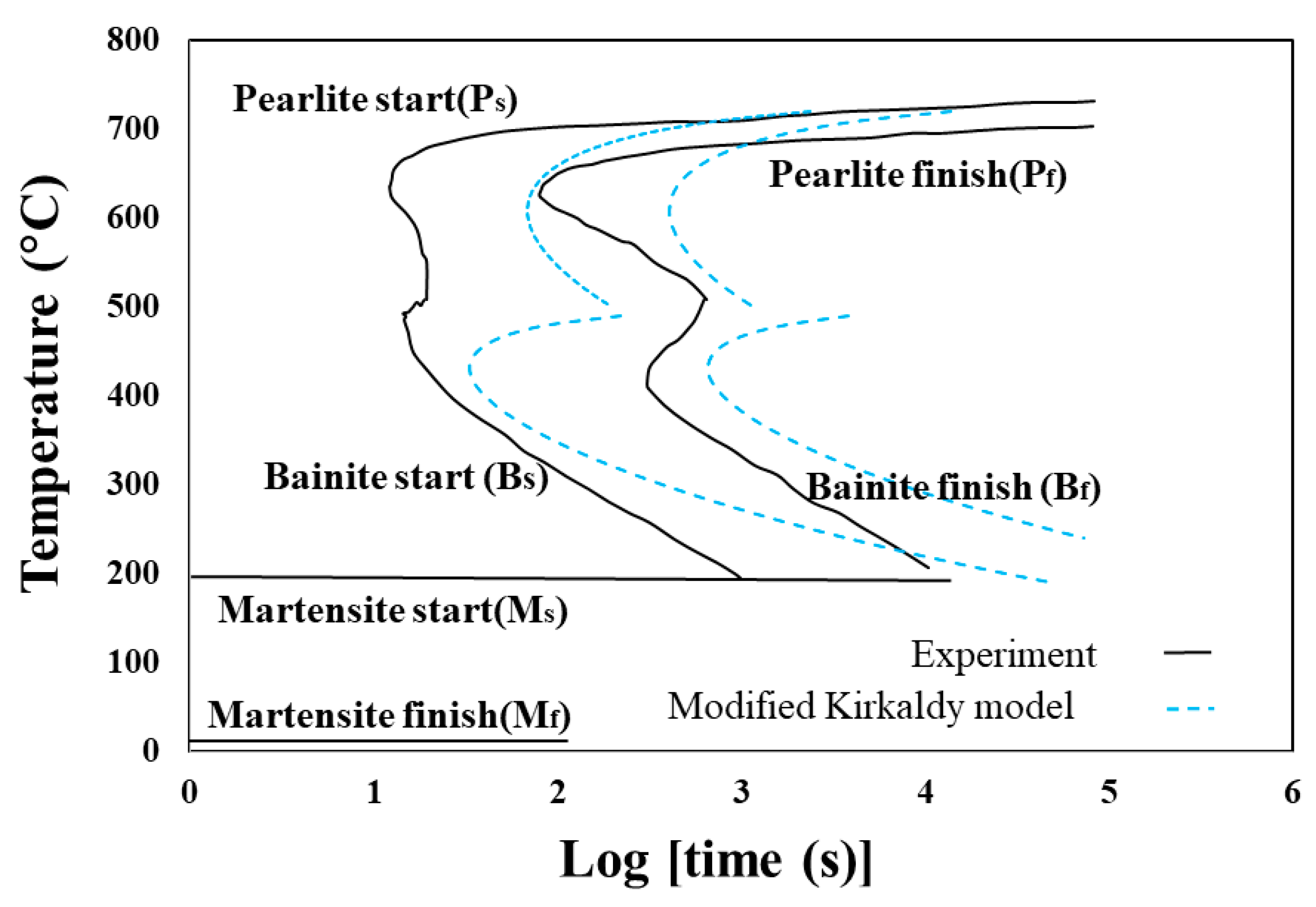
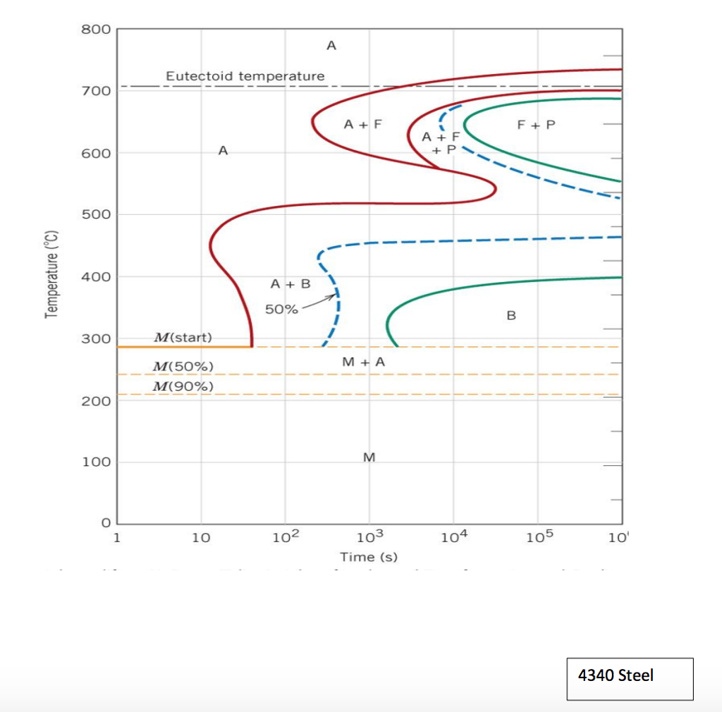
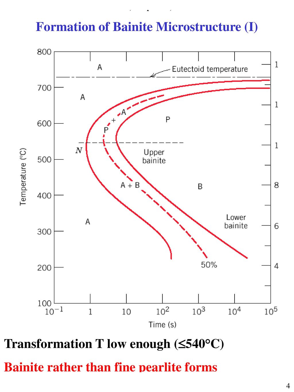
TTT diagram gives Nature of transformation-isothermal or athermal (time independent) or mixed Type of transformation-reconstructive, or displacive Rate of transformation Stability of phases under isothermal transformation conditions Temperature or time required to start or finish transformation Qualitative information about size scale of product Isothermal transformation diagrams (also known as time-temperature-transformation (TTT) diagrams) are plots of temperature versus time (usually on a logarithmic scale).Time-temperature-precipitation diagrams and time-temperature-embrittlement diagrams have also been used to represent kinetic changes in steels. Time-temperature isothermal transformation (TTT) diagram for AISI type 6150 carbon steel, austenitized at 850°C. Continuous cooling transformation (CCT) diagrams Measure the extent of transformation as a function of time for a continuously decreasing temperature. In other words a sample is austenitised and then cooled at a predetermined rate ... 2.26 Off-Eutectoid Isothermal Transformation (IT) Diagrams 7:18. 2.27 4340 Isothermal Transformation (IT) Diagram 5:12. Taught By. Thomas H. Sanders, Jr. Regents' Professor. Try the Course for Free. Transcript. Explore our Catalog Join for free and get personalized recommendations, updates and offers. ...
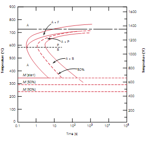
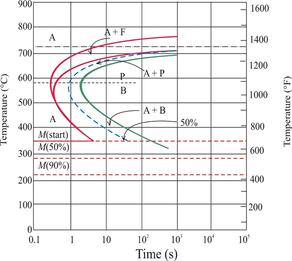
Thermodynamic analysis of isothermal transformation diagrams. A thermodynamic method has been developed to allow the prediction of isothermal transformation diagrams, starting simply from a knowledge of the chemical composition of the steel concerned. The method has been extensively tested and has been shown to be capable of faithfully ... Time Temperature Transformation Diagrams. Time temperature transformation (TTT) diagrams, also known as isothermal transformation diagrams, predict phases and/or microstructure based on how the ... Transcribed image text: An isothermal transformation diagram for a 0.45 wt% C iron-carbon alloy is shown below, with time- temperature paths for (a) 42 percent proeutectoid ferrite and 58 percent coarse pearlite (b) 50 percent fine pearlite and 50 percent bainite (c) 100 percent martensite (d) 50 percent martensite and 50 percent austenite 900 1600 800 AF 1400 700 1200 600 AP Р B 1000 500 AB ... Using the isothermal transformation diagrams (TTT diagram) for various compositions of a steel alloy shown below, answer the following questions. In each case, assume that the specimen begins at 920˚C and that it has been held at this temperature long enough to have achieved a complete and homogeneous austenite structure.
Isothermal Transformation Diagrams
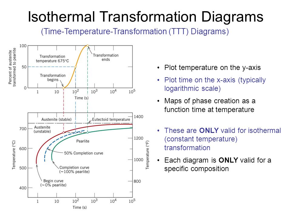
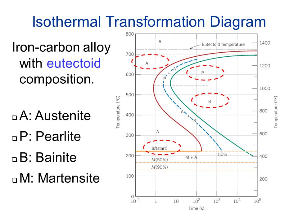
T (Time) T(Temperature) T(Transformation) diagram is a plot of temperature versus the logarithm of time for a steel alloy of definite composition. It is used to determine when transformations begin and end for an isothermal (constant temperature) heat treatment of a previously austenitized alloy.
Isothermal Transformation Diagrams Ppt Video Online Download
Isothermal transformation diagrams (also known as time-temperature-transformation (TTT) diagrams) are plots of temperature versus time (usually on a logarithmic scale).They are generated from percentage transformation-vs time measurements, and are useful for understanding the transformations of an alloy steel at elevated temperatures.. An isothermal transformation diagram is only valid for one ...
Fe Fe3c T T T Diagram Metallurgy For Dummies
Held at that constant ( isothermal) temperature ( T) for a specific time (T) then quenched to room temperature for examination of the transformation (T) products. You may be thinking of CCT ; continuous cooling diagrams ; where a steel sample is austenitized then continuously cooled at some specific rate. Then examined for transformation products.

Solved 2 Given Isothermal Transformation Diagram For A Chegg Com
How to read a ttt diagram. Isothermal transformation diagrams also known as time temperature transformation ttt diagrams are plots of temperature versus time usually on a logarithmic scale. Samples are austenitised and then cooled rapidly to a lower temperature and held at that temperature whilst the amount of transformation is measured ...

Ttt Diagrams 1 The Basic Idea
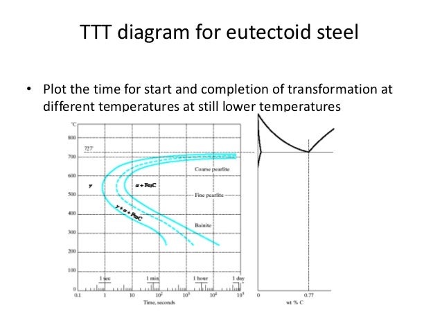
Time-Temperature-Transformation (TTT) diagram or S-curve refers to only one steel of a particular composition at a time, which applies to all carbon steels.This diagram is also called as C-curve isothermal (decomposition of austenite) diagram and Bain's curve.The effect of time-temperature on the microstructure changes of steel can be shown by the TTT diagram.

Diagram Ttt Time Temperature Transformation Muchamad Yosga
Ttt diagrams duration. Isothermal transformation diagrams also known as time temperature transformation ttt diagrams are plots of temperature versus time usually on a logarithmic scale. Davenport and bain were the first to develop the ttt diagram of eutectoid steel. Ttt diagrams have time on the x axis and temperature on the y axis.
Solved Chapter 10 Problem 22qp Solution Materials Science And Engineering An Introduction Eigth Edition Binder Ready Version 8th Edition Chegg Com
2.26 Off-Eutectoid Isothermal Transformation (IT) Diagrams 7:18. 2.27 4340 Isothermal Transformation (IT) Diagram 5:12. Taught By. Thomas H. Sanders, Jr. Regents' Professor. Try the Course for Free. Transcript. Our focus up until this point has been to look at essentially plain carbon steels, but it turns out that there are an abundance of ...

Ttt Diagram Of Steel In Material Science Materials Today
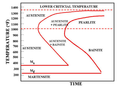
OK, TTT stands for time temperature transformation. Time is on the x-axis (usually logarithmic) and temperature is on the y-axis. Basically you start at any temperature you want and cool and hold at different temperatures to generate different microstructures. There are start and finish temperatures all down this curve, taken from "S" (Avrami ...
Faculty Up Edu
Time Temperature Transformation Diagrams. Time temperature transformation (TTT) diagrams, also known as isothermal transformation diagrams, predict phases and/or microstructure based on how the material is cooled. TTT diagrams have time on the x-axis and temperature on the y-axis. The lines on a TTT diagram represent points at which a material ...
Metals Free Full Text Adjustment Of Isothermal Transformation Diagrams Using Finite Element Optimization Of The Jominy Test
Isothermal transformation diagrams also known as time temperature transformation ttt diagrams are plots of temperature versus time usually on a logarithmic scale. Ttt diagrams have time on the x axis and temperature on the y axis. Solved 2 Read About The T T T Diagram For Steel And Desc

Solved Make A Copy Of The Isothermal Transformation Diagram For A Make A 1 Answer Transtutors
An analytical method for evaluation of quantitative hardenability of eutectoid steels from the corresponding TTT diagram was considered. The isothermal transformation kinetics of pearlite and cooling curves were combined by the additivity rule, and an equation expressing continuous cooling transformation of pearlite has been derived. Based on this equation, simple algorithms for the ...

Ttt Diagram Of Steel In Material Science Materials Today
Using the isothermal Transformation Diagram for An Iron-carbon Alloy Of Eutectoid Composition. solved 10 19 using the isothermal transformation diagram 10 19 using the isothermal transformation diagram for an iron carbon alloy of eutectoid position figure 10 22 specify the nature of the final microstructure in terms of microconstituents present and approximate percentages of each of a small ...

Ttt Diagram Example Engineering Materials Youtube
Figure 5: Diagram showing how measurements of the isothermal transformations of austenite as a function of time and temperature are used to create Isothermal TTT diagrams. Diagrams that describe the transformation of austenite as a function of constant temperature are called Time-Temperature Transformation diagrams.

Solved Isothermal Transformation Diagram For 1080 Plain Chegg Com
I n the last column, we discussed the construction and application of Time Temperature Transformation or Isothermal Transformation diagrams. It was shown how these diagrams could be used to start planning a heat-treatment schedule, and start picking times and temperatures necessary to achieve the desired properties.
1

An Isothermal Transformation Diagram For A Typical 3 5 C 2 5 Si Download Scientific Diagram

Isothermal Transformation Diagram Wikipedia

Isothermal Transformation Diagrams Ppt Video Online Download
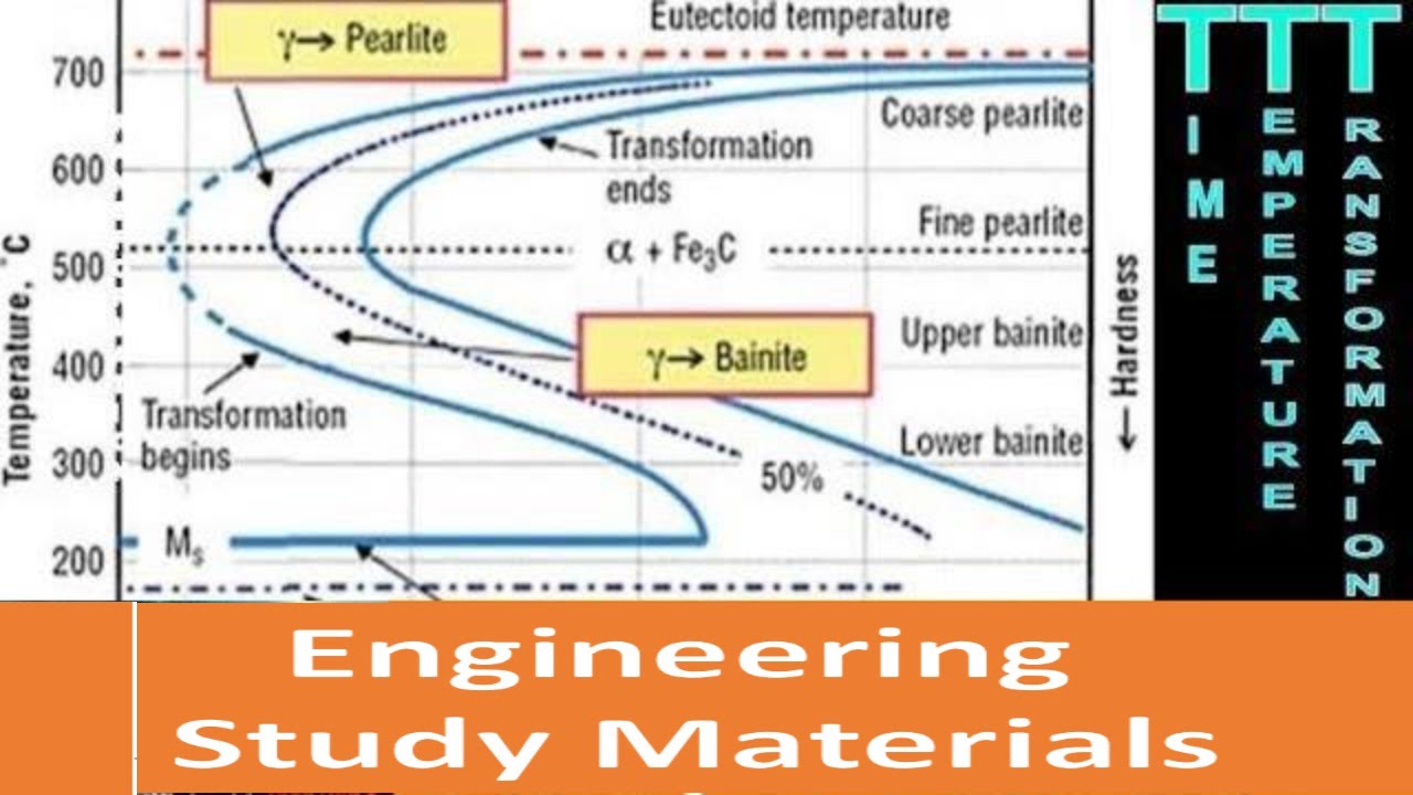
Ttt Diagram Explained Time Temperature Transformation Diagram Curves Engineering Study Materials Youtube

Solved Using The Fe C Isothermal Transformation Diagram For Chegg Com
Fe Fe3c T T T Diagram Metallurgy For Dummies
Time Temperature Transformation Diagram

Ttt Diagrams 1 The Basic Idea
1
Solved 3 Using The Isothermal Transformation Diagram For An Chegg Com
Atlas Of Isothermal Transformation Diagrams U S Steel Amazon Com Books

Atlas Of Isothermal Transformation And Cooling Transformation Diagrams American Society For Metals 9780412653407 Amazon Com Books

Time Temperature Transformation Worksheet Problem Youtube
Ttt Diagram
Isothermal Transformation Or Ttt Diagrams Ppt Download
Phase Transformations Ppt Video Online Download
Faculty Up Edu

Chapter09 Review Pdf Cast Iron Heat Treating
Solved 7 Make A Copy Of The Isothermal Transformation Chegg Com
Fe Fe3c T T T Diagram Metallurgy For Dummies

Teknik Metalurgi Dan Material Logam Continuous Cooling Transformation Cct Diagrams

Pdf Time Temperature Transformation Diagram Within The Bainitic Temperature Range In A Medium Carbon Steel

What Is The Difference Between Cct And Ttt Curve By An Easy Example How They Are Plotted Quora
1
Solved Chapter 10 Problem 20qp Solution Materials Science And Engineering An Introduction Eigth Edition Binder Ready Version 8th Edition Chegg Com

Isothermal Transformation Behavior And Microstructural Evolution Of Micro Alloyed Steel Intechopen

Continuous Cooling Transformation Wikipedia

Ttt Diagram Basic Ttt Diagram For Steel Eutectoid Steel

Oneclass Using The Supplied Isothermal Transformation Diagram For An Irona Carbon Alloy Of Eutectoi
0 Response to "44 how to read isothermal transformation diagram"
Post a Comment