43 motorcycle tachometer wiring diagram
A tachometer is a device that measures the rotation speed of the engine of your motorcycle, and displays this information to you in an easy-to-read fashion. This provides the rider with a greater understanding of the work the engine is doing, as well as information on when to shift and a means by which to ensure good ... What kind of wire does an engine tachometer use? This +12 V terminal will be supplied from the ignition switch for the engine and is often purple (PU) in color. The "G" terminal is the instrument ground and will be either black or yellow in color depending upon the vintage of the boat. Finally, the tachometer sending or "PUL" wire will ...
Wiring Diagram Of Motorcycle Http Bookingritzcarlton Info Wiring Diagram Of Motorcycle Tachometer Boat Wiring Diagram . Vdo spin lok clamp or vdo mounting bracket and nuts 1 5. Vdo volt gauge wiring diagram. Connect the harness according to the following wiring matrix. If using the warning led in the gauge and a vdo sender with warning contact ...

Motorcycle tachometer wiring diagram
Motorcycle Tachometer Wiring Diagram from static-cdn.imageservice.cloud. Print the wiring diagram off plus use highlighters to trace the signal. When you make use of your finger or perhaps the actual circuit with your eyes, it is easy to mistrace the circuit. 1 trick that We 2 to printing a similar wiring plan off twice. 4. Connect the wire from the light switch to the remaining terminal on the lamp socket. 5. Connect the wire from the ignition coil, as shown in Diagram D to the #2 terminal on t 6. At this point, the installation and wiring of your tachometer is complete. Reconnect the negative batter you disconnected before beginning this installation. The Honda VTX Motorcycle Forums. Honda VTX 1300 Forums. tachometer diagram. Jump to Latest Follow ... Joined Nov 27, 2016 · 169 Posts . Discussion Starter · #1 · May 5, 2017. does anyone have a wiring diagram for a tachometer for a vtx 1300 if the bike can even support a tach. Save Share. Reply.
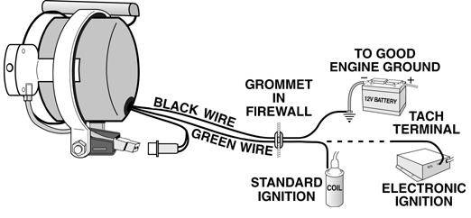
Motorcycle tachometer wiring diagram. Dan's Motorcycle "Wiring Diagrams". Reading Wiring Diagrams. "And God said, Let there be light: and there was light. And God saw the light, that it was good: and God divided the light from the darkness." Genesis 1:3-4. ¶ Every motorcycle has a Wiring System. Every one of them, bar none. Without a Wiring System there will be no light. Wiring Diagram For Aftermarket Tachometer ... engine, such as Honda bike and mostly motorcycle engine today. If it is used on a motorcycle with one cylinder two-stroke engine, this tachometer will read twice the actual engine speed (RPM). ... the following schematic illustrates three main wires of tachometer wiring. See Diagram F. III. Calibrating the Tachometer a second piece of wire (long enough to reach the light switch) into another spade connector. Attach this con-nector to a terminal on the remaining lamp socket, which will be referred to as Socket B. 9. Reconnect the battery and turn on the ignition to make sure the tachometer is working. When you ... Connect the blue wire to the same switched 12 volt power source as the red wire if you want the tach light to be on continuously, or to the light terminal on the ignition switch. 4. Connect the green wire on the tach to the negative side of the coil, the tach lead on the ignition, or to a tach adapter depending on your application.
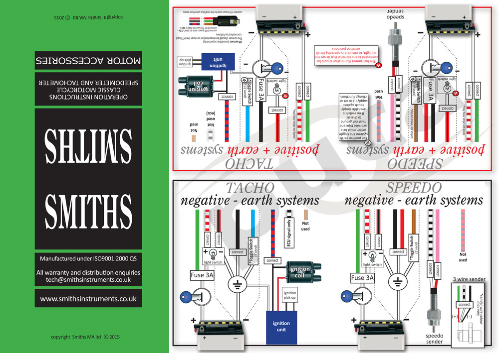
To Smiths Electronic Tachometers. Tachometer wiring how to install a smithsclassic volvo 1800 diagram tech wiki datsun duraspark 2 ford tachometers complete guide rs installation and operations ranger official website of the bcoie chapter another thread mgb gt forum instructions for 5 sw em smith s in your car idiots koso tach smiths electronic electric mga vdo performance instruments yamaha ... Link to buy the Rpm meter1.Chrome rpm meter-http://amzn.to/2sVVO872.Black rpm meter-http://amzn.to/2s4Iq1u3.Rpm meter with fuel indicator-http://amzn.to/2rkY... Wiring diagram for tachometer. 2005 Triumph America wired for tach in gas tank console but not equipped. Adding aftermarket tach, but need wiring diagram for the three vacant plugs under console. Clicking this will make more experts see the question and we will remind you when it gets answered. Mar 18, 2021 - Universal Motorcycle Speedometer Wiring Diagram and Wiring Aftermarket Tacho? - Page - 17+ Universal Motorcycle Speedometer Wiring Diagram .Universal Motorcycle Speedometer Wiring Diagram and Wiring Aftermarket Tacho? - Page - Wiringg.net
Jul 21, 2021 - Universal Motorcycle Speedometer Wiring Diagram and Wiring Diagram For Odometer - Types Of Electrical Wiring - 17+ Universal Motorcycle Speedometer Wiring Diagram .Universal Motorcycle Speedometer Wiring Diagram and Wiring Diagram For Odometer - Types Of Electrical Wiring - Wiringg.net Wiring configuration is different than most Tachometers.20150213 200330 80mm 11000 Rpm Tachometer. Defi Advance A1 Egt Gauge 1100c. Defi Link Meter Summary Features Exciting Products By Ns An. Defi Vsd Wiring Diagram Ditdottudit. Defi Link Meter Advance Bf Tachometer Gauge White Face 80mm Df11001. Installation For Personnel Warning Caution Defi Link Vsd Concept User Manual Page 3 16. Universal Motorcycle Tachometer Wiring Diagram - wiring diagram is a simplified adequate pictorial representation of an electrical circuit. It shows the components of the circuit as simplified shapes, and the capacity and signal connections between the devices. A wiring diagram usually gives information nearly the relative viewpoint and ...
How To Install A Tachometer Onallcylinders
If you want to get another reference about Digital Speedometer Circuit Diagram for Motorcycle Please see more wiring amber you will see it in the gallery below. ... dakota digital speedometer sensors motorcycle tachometer gauge first test kege yamaha fz16 speedometer back light mods 11k rpm lcd tachometer ebay universal 2 in 1 motorcycle led ...

Solved Tachometer Wiring Diagram Fixya
) Wiring diagram for rectifier regulator Date: nick: hensiza bombardier rotax wiring diagrams Download: rotax bombardier wiring at Marks Web of Books and. Rotax / Dual CDI Tachometer. Installation Instructions: Additional wire Route wires away from hot surfaces and moving parts using wire ties as needed .

Wiring Diagram For Aftermarket Tachometer
Tachometer installation can be as simple as connecting the tach's sending wire to the negative side of the ignition coil, while other ignition systems feature a dedicated tach sending circuit. In either case, installing the tachometer incorrectly can cause significant damage to both the tach and ignition system.
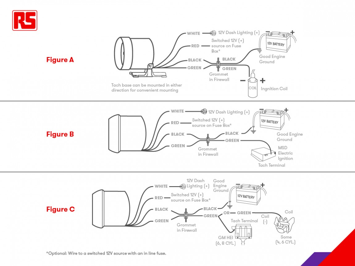
Tachometers A Complete Guide Rs Components
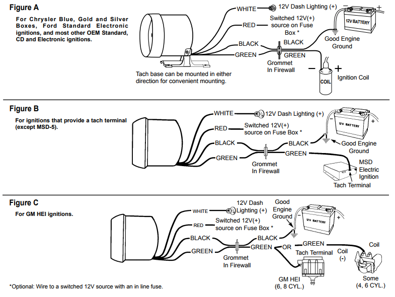
This tachometer is factory calibrated for 8 cylinder engines. For operation on 4 or 6 cylinder engines, a switch adjustment must be made. Wiring Connect the tachometer wires as shown. The wiring diagram shown is a typical installation. For Chrysler Blue, Gold and Silver Boxes, Ford Standard Electronic ignitions, and most other OEM Standard,

Universal Digital Lcd Backlight Motorcycle Speedometer Odometer Tachometer Gauge Motorcycle Wiring Happy Birthday Messages Motorcycle
on Iztoss Tach Wiring Diagram. Ambuker KMH MPH rpm LCD Digital Speedometer Tachometer .. Take the digital English Manual for reference, if you do not understand to install. This is part 1 of 2 for this rpm ebay tacho. Its a good tacho but typically it comes without a wiring diagram or instructions,. Hopefully this.
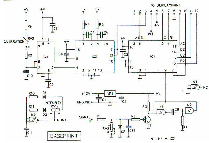
Digital Tachometer Rpm Meter Electronic Schematic Diagram
Tach Wiring Diagram - dixco tach wiring diagram, harley tach wiring diagram, pro tach wiring diagram, Every electric arrangement is composed of various distinct pieces. Each component ought to be placed and connected with other parts in particular manner. Otherwise, the arrangement will not work as it ought to be.

Universal Motorcycle Led Lcd Digital Speedometer Tachometer Odometer Oil Gauge Ebay
356 Tach Wiring | Wiring Diagram - Tachometer Wiring Diagram. Wiring Diagram arrives with a number of easy to follow Wiring Diagram Instructions. It is intended to assist all of the average person in building a proper system. These instructions will be easy to comprehend and apply.

Buy Rpm Km H Motorcycle Odometer Tachometer Speedometer Stainless Steel Gauge Led Gear Indicator 205x98x81mm At Affordable Prices Free Shipping Real Reviews With Photos Joom
Yamaha LT1 LT2 100 Electrical Wiring Diagram Schematics 1971 1972 1973 HERE. Yamaha MT-01 1700 Electrical Wiring Harness Diagram Schematic 2005 to 2012 HERE. Yamaha PW50 PW 50 Electrical Wiring Harness Diagram Schematics HERE. Yamaha QT50 Yamahopper QT 50 Electrical Wiring Diagram Schematics 1979 to 1992 HERE.

Gauge Speedometer Harley Davidson Wiring Diagram Motorcycle Speedometer Electronics Electrical Wires Cable Schematic Png Pngwing
Moved Temporarily The document has moved here.

Motorcycle Tachometer For All Dual Fire Ignitions Harley Tach Universal Fit Auto Parts Accessories Motorcycle Parts Smarf Kr
Iztoss Universal LED Motorcycle Tachometer+Odometer Speedometer Gauge. by IZTOSS. Buy IZTOSS MPH/KMH MPH/kmh rpm LCD Digital Speedometer Tachometer Odometer for 4 stroke 1/2/4 So I spent the weekend re-wiring my bike and afterwards I attempted to wire this gauge in.
Tachometer Wiring Plug Color Codes Kawasaki Klr Forum
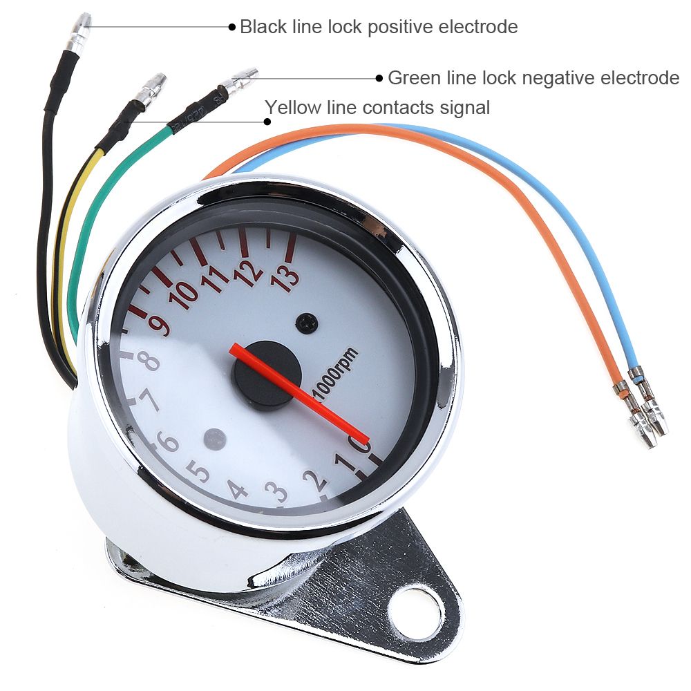
1. Mount tach base firmly to reduce vibration, wear and tear. 2. Avoid contact of the tach with windshield or other objects to maintain rubber shock absorbing feature. 3. A 12 V power source MUST be used to power this tachometer. A 12 V motorcycle battery is a good alternative for cars without batteries.
How To Wire Aftermarket Speedometer Tachometer Kzrider Forum Kzrider Kz Z1 Z Motorcycle Enthusiast S Forum
The Honda VTX Motorcycle Forums. Honda VTX 1300 Forums. tachometer diagram. Jump to Latest Follow ... Joined Nov 27, 2016 · 169 Posts . Discussion Starter · #1 · May 5, 2017. does anyone have a wiring diagram for a tachometer for a vtx 1300 if the bike can even support a tach. Save Share. Reply.
5 Wire Tachometer Help Triumph Rat Motorcycle Forums
4. Connect the wire from the light switch to the remaining terminal on the lamp socket. 5. Connect the wire from the ignition coil, as shown in Diagram D to the #2 terminal on t 6. At this point, the installation and wiring of your tachometer is complete. Reconnect the negative batter you disconnected before beginning this installation.
Best And Cheapest Motorcycle Instruments General Purpose 13000 Rpm 12v Motorcycle Tachometer Odometer Gauge White Chassis 5 Wire Speed Indicator Mot 107 For Sale Dhgate Com
Motorcycle Tachometer Wiring Diagram from static-cdn.imageservice.cloud. Print the wiring diagram off plus use highlighters to trace the signal. When you make use of your finger or perhaps the actual circuit with your eyes, it is easy to mistrace the circuit. 1 trick that We 2 to printing a similar wiring plan off twice.

Motorcycle Rpm Gauge Speedometer Speedo Meter Led Chopper Bobber Cafe Racer Chrome

Easy Motorcycle Speedometer Wiring How To Diagrams Youtube
How To Connect A Tachometer

Installation Of A Rev Counter On Your Motorcycle In 2 Easy Steps

Wiring Diagram For Aftermarket Tachometer
Adding Aftermarket Tach Where To Pick Up Rpm Signal Kawasaki Vulcan Forum
Tachometer Wiring Plug Color Codes Kawasaki Klr Forum
Digital Chronometric Speedometer And Tachometer Tech Help For Smiths Digital Ma British Gauge

12v 15000rpm Universal Motorcycle Digital Speedometer Odometer Tachometer 299kmh China Gps Speedometer Tachometer Made In China Com

Searon Backlit Digital Resettable Inductive Tacho Hour Meter Tachometer For Motorcycle Marine Boat Atv Snowmobile Generator Mower Amazon Com Au Automotive
How To Wire Aftermarket Speedometer Tachometer Kzrider Forum Kzrider Kz Z1 Z Motorcycle Enthusiast S Forum

Reddragonfly 199 Km H 12000 Rpm Lcd Digital Speedometer Tachometer Odometer Mph Kmh For Honda Motorcycle Sctoor Go Honda Motorcycle Tachometer Cafe Racer
Universal Digital Speedometer Motorcycle Wiring Diagram
Chinese Tacho Kzrider Forum Kzrider Kz Z1 Z Motorcycle Enthusiast S Forum

Autometer Jr 6650 Briggs Engine Tachometer Wiring Instructions Auto Meter Youtube

17 Universal Motorcycle Speedometer Wiring Diagram Motorcycle Diagram Wiringg Net Odometer Types Of Electrical Wiring Trailer Light Wiring

Car Wiring Diagram Speedometer Tachometer Speedometer Kabel Kabel Listrik Mobil Motor Png Pngwing
Buy Samdo Digital Speedometer 199 Km H 6 Gear Lcd Universal Motorcycle Speedometer Gauge With Odometer 13000 Rpm Tachometer Online In Hungary B0711mzwp2

Buy Qiilu Universal Motorcycle Led Digital Speedometer Tachometer Speed Gauge Oil Level Meter Black Online In Indonesia B07dg18mzj

Digital Speedo Install Help Custom Fighters Custom Streetfighter Motorcycle Forum

Buy Samdo Motorcycle Speedometer 299 Kmh Mph 7 Color 14000rpm Tachometer Atv Quad Frenzy Universal Digital Speedometer Online In Kazakhstan B072bb495t

Buy Dkmotork 0011 Digital Gauge Motorcycle Speedometer Tachometer Odometer Universal With Multi Function Indicator Light Display Black Online In Slovakia B07ww3l3y8
Cbz Xtreme Wiring Diagram Off 62 Medpharmres Com
Large Diameter White Faced Tachometer For Scout Indian Motorcycle Forum

Buy Searon Digital Tach Hour Meter Tachometer Rpm Counter For Snowmobile Skis Motor Bike Go Kart Lawn Mower Online In Hungary B01h5ecbz0

Gauge Tachometer Motorcycle Electronics Motor Vehicle Speedometers Harley Speedometer Wiring Diagram Electronics Car Motorcycle Png Pngwing

94 Gsxr Rpm Wire Custom Fighters Custom Streetfighter Motorcycle Forum
Aftermarket Mini Tach Installation Triumph Rat Motorcycle Forums

Buy Bluerice 199 Kph Mph Universal Motorcycle Speedometer Digital Lcd Odometer Tachometer Online In Indonesia B07lckjk4b
0 Response to "43 motorcycle tachometer wiring diagram"
Post a Comment